


Chapter 1: Introduction
1-3
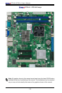
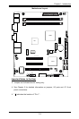
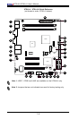
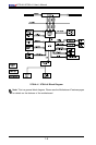
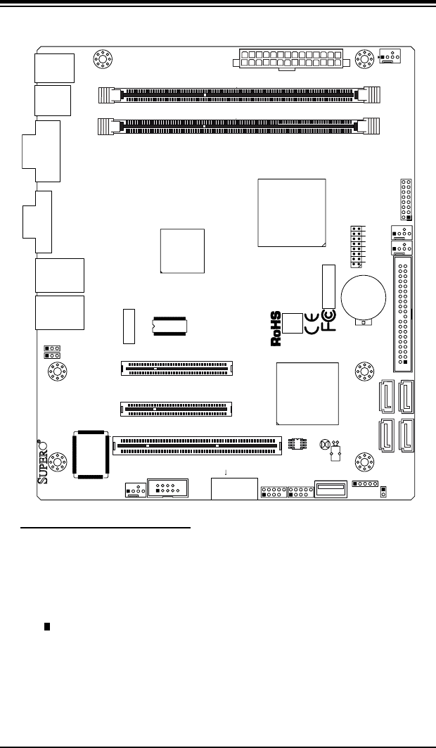
Motherboard Layout
Important Notes to the User
Jumpers not indicated are for testing only. •
See Chapter 2 for detailed information on jumpers, I/O ports and JF1 front •
panel connections.
" " indicates the location of "Pin 1". •
JF1
J13
JL1
R52
R53
JPL1
JPL2
FAN3
FAN1
FAN_NB
41
FAN2
J3
J51
J46
JP5
JP4
BT1
JBT1
TP_ICH3
Tested to Comply
With FCC Standards
FOR HOME OR OFFICE USE
X7SLA-H
DESIGNED IN USA
NIC
I-SATA3
I-SATA2
I-SATA1
I-SATA0
SLOT7 PCI-E X4 in X8
SLOT6 PCI-E X8
USB2/3
COM2
USB4/5
USB6
JBT1:CMOS CLEAR
IDE
SLOT5 PCI 33MHZ
1-2:ENABLE
2-3:DISABLE
JPL1-2:LAN1/2
INTRUSION
JL1:CHASSIS
LAN2
LAN1
VGA
COM1
X
LED
PWRHDD
NIC
/FF
OHRSTPWR ON
1
JF1
DIMM1A
DIMM1B
JPW1
JPW2 for Device Power Only
KB/MOUSE
USB7
USB0/1
CPU
945GC
ICH7R