


2-6
X7SLA-L/X7SLA-H User's Manual
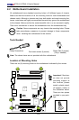
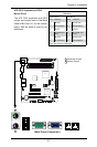
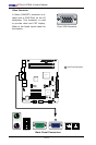
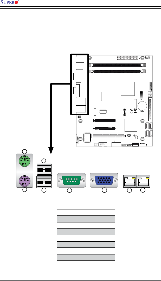
I/OPortLocationsandDenitions
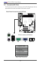
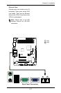
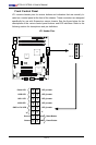
2-5 Connectors/I/O Ports
The I/O ports are color coded in conformance with the PC 99 specication. See the
gure below for the colors and locations of the various I/O ports.
Back Panel Connectors and I/O Ports
2
4
7
1
3
5
6
8
1. Keyboard (Purple)
2. PS/2 Mouse (Green)
3. USB Port 0
4. USB Port 1
5. COM 1 (Green)
6. VGA (Blue)
7. LAN1
8. LAN 2 (X7SLA-H only)
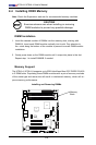
JF1
J13
JL1
R52
R53
JPL1
JPL2
FAN3
FAN1
FAN_NB
41
FAN2
J3
J51
J46
JP5
JP4
BT1
JBT1
TP_ICH3
Tested to Comply
With FCC Standards
FOR HOME OR OFFICE USE
X7SLA-H
DESIGNED IN USA
NIC
I-SATA3
I-SATA2
I-SATA1
I-SATA0
SLOT7 PCI-E X4 in X8
SLOT6 PCI-E X8
USB2/3
COM2
USB4/5
USB6
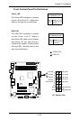
JBT1:CMOS CLEAR
IDE
SLOT5 PCI 33MHZ
1-2:ENABLE
2-3:DISABLE
JPL1-2:LAN1/2
INTRUSION
JL1:CHASSIS
LAN2
LAN1
VGA
COM1
X
LED
PWRHDD
NIC
/FF
OHRSTPWR ON
1
JF1
DIMM1A
DIMM1B
JPW1
JPW2 for Device Power Only
KB/MOUSE
USB7
USB0/1
CPU
945GC
ICH7R
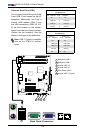
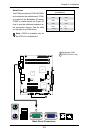
Back Panel Connectors