


2-12
X7SLA-L/X7SLA-H User's Manual
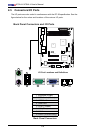
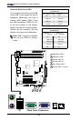
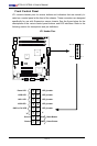
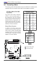
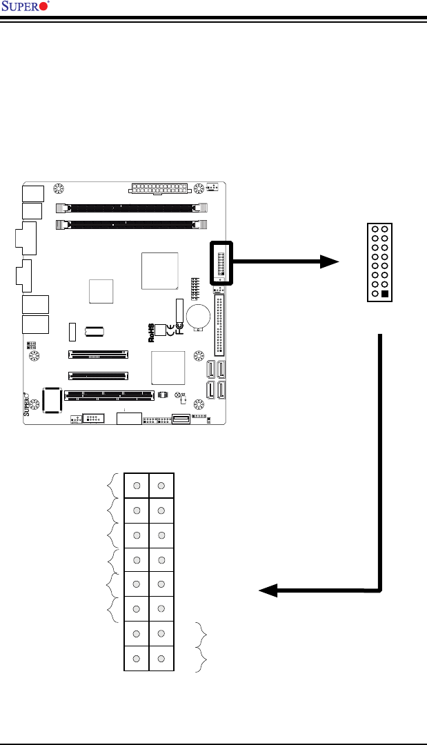
Front Control Panel
JF1 contains header pins for various buttons and indicators that are normally lo-
cated on a control panel at the front of the chassis. These connectors are designed
specically for use with Supermicro server chassis. See the gure below for the
descriptions of the various control panel buttons and LED indicators. Refer to the
following section for descriptions and pin denitions.
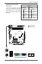
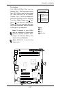
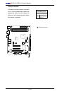
JF1 Header Pins
JF1
J13
JL1
R52
R53
JPL1
JPL2
FAN3
FAN1
FAN_NB
41
FAN2
J3
J51
J46
JP5
JP4
BT1
JBT1
TP_ICH3
Tested to Comply
With FCC Standards
FOR HOME OR OFFICE USE
X7SLA-H
DESIGNED IN USA
NIC
I-SATA3
I-SATA2
I-SATA1
I-SATA0
SLOT7 PCI-E X4 in X8
SLOT6 PCI-E X8
USB2/3
COM2
USB4/5
USB6
JBT1:CMOS CLEAR
IDE
SLOT5 PCI 33MHZ
1-2:ENABLE
2-3:DISABLE
JPL1-2:LAN1/2
INTRUSION
JL1:CHASSIS
LAN2
LAN1
VGA
COM1
X
LED
PWRHDD
NIC
/FF
OHRSTPWR ON
1
JF1
DIMM1A
DIMM1B
JPW1
JPW2 for Device Power Only
KB/MOUSE
USB7
USB0/1
CPU
945GC
ICH7R
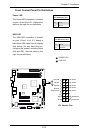
Power Button
OH/Fan Fail LED
1
NIC1 LED
Reset Button
2
HDD LED
Power LED
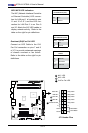
Reset
PWR
LED_Anode+
LED_Anode+
LED_Anode+
LED_Anode+
Ground
Ground
X
X
NIC2 LED
LED_Anode+
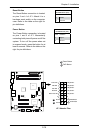
Pin 15
Pin 16
Pin 1Pin 2