


2-2
X7SLA-L/X7SLA-H User's Manual
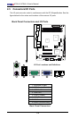
JF1
J13
JL1
R52
R53
JPL1
JPL2
FAN3
FAN1
FAN_NB
41
FAN2
J3
J51
J46
JP5
JP4
BT1
JBT1
TP_ICH3
Tested to Comply
With FCC Standards
FOR HOME OR OFFICE USE
X7SLA-H
DESIGNED IN USA
NIC
I-SATA3
I-SATA2
I-SATA1
I-SATA0
SLOT7 PCI-E X4 in X8
SLOT6 PCI-E X8
USB2/3
COM2
USB4/5
USB6
JBT1:CMOS CLEAR
IDE
SLOT5 PCI 33MHZ
1-2:ENABLE
2-3:DISABLE
JPL1-2:LAN1/2
INTRUSION
JL1:CHASSIS
LAN2
LAN1
VGA
COM1
X
LED
PWRHDD
NIC
/FF
OHRSTPWR ON
1
JF1
DIMM1A
DIMM1B
JPW1
JPW2 for Device Power Only
KB/MOUSE
USB7
USB0/1
CPU
945GC
ICH7R
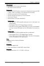
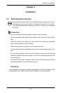
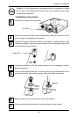
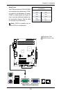
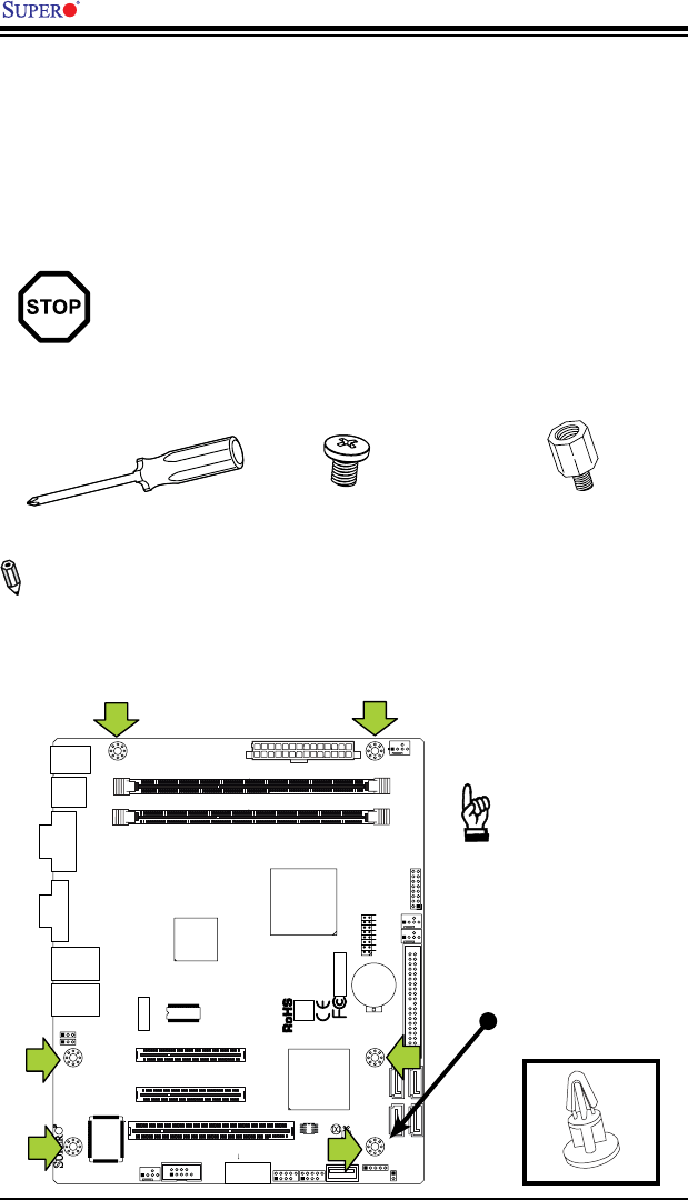
Important: If the chas-
sis does not provide
mounting support at
this location, please
install a plastic stand-
off support, similar to
the illustration below.
There are two pieces
provided in your pack-
age.
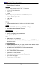
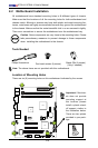
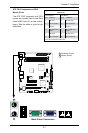
2-2 Motherboard Installation
All motherboards have standard mounting holes to t different types of chassis.
Make sure that the locations of all the mounting holes for both motherboard and
chassis match. Although a chassis may have both plastic and metal mounting fas-
teners, metal ones are highly recommended because they ground the motherboard
to the chassis. Make sure that the metal standoffs click in or are screwed in tightly.
Then use a screwdriver to secure the motherboard onto the motherboard tray.
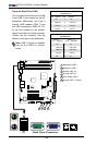
Caution: Some components are very close to the mounting holes. Please
take precautionary measures to prevent damage to these components
when installing the motherboard to the chassis.
Tools Needed
Philips Screwdriver
Pan head screws (6 pieces)
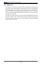
Location of Mounting Holes
There are six (6) mounting holes on this motherboard indicated by the arrows.
Stand Offs (6 pieces)
(Only if needed)
Note: The above items are not provided with this motherboard.