


Chapter 1: Introduction
1-5
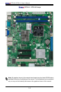
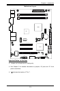
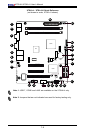
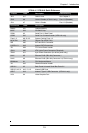
X7SLA-L / X7SLA-H Quick Reference
Jumpers Label Description Default Setting
JBT1 #17 CMOS Clear See Chapter 2
JPL2 #8 GLAN 2 Enable (X7SLA-H only) Pins 1-2 (Enabled)
JPL1 #7 GLAN 1 Enable Pins 1-2 (Enabled)
Connectors Label Description
Battery #21 Onboard Battery
BIOS #19 SPI BIOS Chip
COM1 #3 Serial Port 1, Back Panel
COM2 #10 Serial Port 2 internal header (X7SLA-H only)
Fans 1~3 #9, 22, 25 System Cooling Fans 1~3
MCH FAN #23 Chipset Fan (MCH FAN)
IDE #20 IDE Hard Drive Connector
I-SATA 0~3 #18 Internal SATA Connectors
JF1 #24 FP Control Panel Header
JPW1 #26 ATX 24-pin Power Connector (Required)
JPW2 #11 4-pin Power Connector (for device power only)
LAN1 #5 Ethernet RJ45 (GB LAN) Connector 1
LAN2 #6 Ethernet RJ45 (GB LAN) Connector 2 (X7SLA-H only)
KB/Mouse #1 PS/2 Keyboard/Mouse
JL1 #16 Chassis Intrusion Header
USB 0/1 #2 Back Panel Universal Serial Bus Ports 0/1
USB 2/3, 4/5, 6 #12, 13, 15 Internal USB Ports
USB 7 #14 Internal "Type A" USB Connector (X7SLA-H only)
VGA #4 Video Graphics Port