


A-12 Configuration Quick Reference
Configuration
Quick-Reference
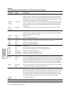
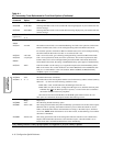
CTS
CTS Control
Determines how the modem sets the CTS signal. The modem signals the DTE with CTS on
EIA/TIA 232-D Pin 5 (V.24 Circuit 106). The CTS Signal discussed here is the state of the
CTS signal after the setting of the modem’s RTS option has been followed. For CTS to follow
the RTS signal from the DTE, set the modem RTS= Normal.
AT & R 0/
AT
*
CT3
=AsyncSync CTS is on in asynchronous mode. CTS is off in synchronous, ACU mode. If the data transfer
mode is synchronous, CTS is off during training/retraining and follows RTS in data mode.
When CTS follows RTS in data mode, the setting of the RTS/CTS Delay option applies (if
Mode=Direct).
AT & R 1/
AT
*
CT0
CTS=High CTS remains high at all times. Use this option with RTS/CTS or DTR/CTS Flow control.
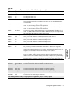
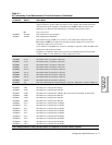
DSR
DSR Control
Determines how the modem sets the DSR signal. The modem signals the DTE with DSR on
EIA/TIA 232-D Pin 6 (V.24 Circuit 107).
AT&S0 =High DSR is always on.
AT&S1 =Normal DSR is controlled by the modem.
AT & T0
TEST
=End Test
Test
Ends the test currently in progress for each test listed below (except retrain).
AT&T1 =LAL Initiates a local analog loopback test.
AT&T3 =LDL Initiates a local digital loopback test.
AT & T4
Accept RDL
=On
Accept RDL
The local modem can be put into a remote digital loopback test.
AT&T5 =Off The local modem cannot be put into a remote digital loopback test.
AT&T6 TEST=RDL Initiates a remote digital loopback test.
AT&T7 TEST=RDL Pat Initiates a remote digital loopback pattern test.
AT&T8 TEST=LAL Pat Initiates a local analog loopback pattern test.
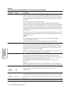
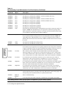
AT & V 0
Status
Long Form
Status
Modem Status Display
Lets you view modem status information, on the control terminal, in long form. The display
shows operating status, DTE/DCE rate/status, asymmetric rates status, connect message status,
the data form, throughput-delay minimization status, error correction status, data compression
status, EIA/TIA signal status, disconnect reasons, the software revision level, and CQMS
parameters. The long form also shows front panel options and corresponding AT commands.
AT&V1 Short Form
Status
Lets you view modem status information, on the control terminal, in short form. This displays
a summary of AT command settings and S-register values.
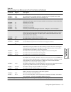
Save Changes
Save Changes
When using AT Commands or front panel options to alter modem settings, if you do not save
the changes, the modem does not enter them into memory. After you have selected the option
set for your application (using the ATZn Command), and modified configuration settings,
enter: AT&W
n
where
n
=(Option Set) 1 through 4. The modem displays Saving Options, then
Save Completed! signifying that the option set has been saved in nonvolatile memory.
AT & W0 /
AT & W1
=1 Save changes to Option Set 1.
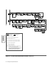
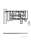
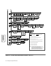
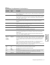
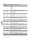
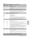
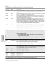
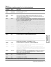
Table A-1.
AT Commands, Cross-Referenced to Front Panel Options (Continued)
AT
Command
Parameter &
Option Description
Gray shading indicates country-specific options. See Appendix C for your country’s options.