


Getting Started 3-3
Getting Started
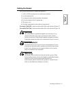
IMPORTANT: To use the front panel keys, the modem must be connected to an AC
power source, the rear panel power switch must be turned on, and rear panel DIP
Switches #3 and #6 must be set to the Off (up) position. See Chapter 2 for details.
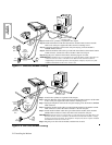
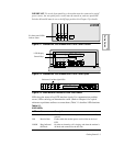
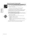
Figure 3-1. Standalone 3260 Modem with Front Cover Closed
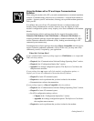
Figure 3-2. Standalone 3260 Modem with Front Cover Open
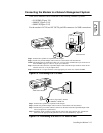
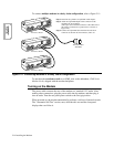
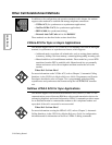
Figure 3-3. 3260 Modem Enclosure Card Front Panel
LEDs show the status of key DTE interface signals. If a communication problem
occurs, LEDs can help you determine the cause. (Refer to Chapter 6 for a quick
reference to problems and how to correct them.) Table 3-1 describes LED functions.
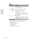
Table 3-1.
326X LEDs
LED Name Description
TD Transmit Data Flashes when the modem accepts data from the local DTE, to
transmit.
RD Receive Data Flashes when the modem passes received data to the local
DTE.
RI/OH Ring Indicator/
Off-Hook
On when an incoming call is ringing, and when the modem is
off-hook and connected to the dial line.
RD TR RI/OH
TD CD RC/NC
3260
104 108 125
103 109
Six front-panel LEDs
indicate status
RD TR RI/OH
TD CD RC/NC
103
104
109
108 125
326x Ready
RETURN ENTER
LCD Display
Control Keys
326x Ready
RETURN DOWN ACROSS ENTER
TD
TR
RI/OH
RD
CD
RC/NC
A/B ALM
103 104
109 108
125
Enclosure Card has eight LEDs