


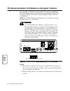

Cabling and Interface Pinouts B-7
Interface
Pinouts
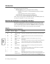
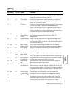
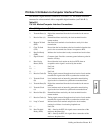
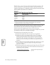
NC (Network Control) Port Pinouts
Table B-3 describes the pinouts for the IN and OUT NC (Network Control) ports.
Cabling
This section provides important information about cabling and operating the modem
at DTE rates greater than 19.2 kbps.
NOTE: 326XFA ST and 326XFA ST-SDC Series Modems are referred to as 326X
Series Modems here.
Caution
When operating the modem at DTE rates higher than 19.2
kbps, carefully follow the information here to determine the
cables to use with your application. For the modem to operate
as specified, Telenetics has indicated the maximum capaci-
tance of cables to be used when operating at data rates higher
than 19.2 kbps. If this method is not followed, your modem
may cause errors in data transmission. Telenetics makes no
guarantee of proper modem operation if you do not use a cable
with the correct capacitance.
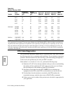
Cable Considerations
Telenetics has specified a maximum allowable cable capacitance for use with the
expanded data rates of 326X modems. Yo umust determine the correct capacitance
of the cable you intend to use with the modem.
Table B-3.
Network Control Port Connector Pinouts
Pin In Out
1 Not Connected User Special In
2 TXD In TXD Out
3 RXD In RXD Out
4RTS In RTS Out
5 Not Connected Not Connected
6 Not Connected User Special Out
7 Ground Ground
8 DCD In DCD Out
“In” signals use a DCE-type interface. This type of interface connects directly to the
DTE-type interface provided by Telenetics’ Network Management Systems.
“Out” signals use a DTE-type interface. This type of interface may connect to a Telenetics
or Motorola network-managed product.