


Cabling and Interface Pinouts B-5
Interface
Pinouts
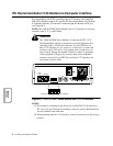
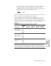
ITU Rate V.35 Modem-to-Computer Interface Pinouts
The modem’s digital interface conforms to ITU Rate V.35. The modem should be
connected to a data terminal with a compatible digital interface (see Table B-1).
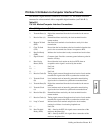
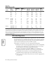
Table B-2.
ITU V.35 Modem/Computer Interface Connections
Pin V.35 Signal Definition
1 Frame Ground Frame (or protective) ground.
2 Transmit Data (A) Digital data transmitted from the local terminal to the remote
modem.
3 Receive Data (A) Demodulated data received by the local terminal from the
remote modem.
4 Request To Send
(RTS)
Sent from local terminal to local modem to ready it for data
transmission.
5 Clear To Send
(CTS)
Passes from the local modem to the local terminal when the data
port is clear to transmit data. Occurs in response to RTS.
6 Data Set Ready
(DSR)
Indicates the local modem is ready to transmit and receive data.
7 Signal Ground Common signal. Provides a common ground reference point for
interface circuitry.
8 Data Carrier
Detect (DCD)
Passed from the local modem to the local DTE when an
acceptable carrier signal is received by the modem.
9 — Not Used.
10 — Not Used.
11 — Not Used.
12 Receive Clock (B) Timing signal extracted from the received carrier. Local modem
transmits this signal to the DTE to synchronize received data.
13 Transmit Clock
(B)
Local modem sends an internally generated transmit timing
signal to the local terminal to synchronize transmitted data.
14 Transmit Data (B) Digital data transmitted from the local terminal to the remote
modem.
15 Transmit Clock
(A)
Local modem sends an internally generated transmit timing
signal to the local terminal to synchronize transmitted data.
16 Receive Data (B) Demodulated data received by the local terminal from the
remote modem.
17 Receive Clock (A) Timing signal extracted from the received carrier. Local modem
transmits this signal to the DTE to synchronize received data.
18 Loop 3 Control Initiated at the local terminal and passed to local modem,
causing it to initiate a local analog loopback test.
19 — Not Used.
20 Data Terminal
Ready (DTR)
108.1—Sent by the DTE, this signal causes connection of the
modem to the phone line.
108.2—Sent by the DTE, this signal allows connection of the
modem to the phone line.