


A-24 Configuration Quick Reference
Configuration
Quick-Reference
AT
*
MN5 =9600
AT
*
MN6 =12.0
AT
*
MN7 =14.4
AT
*
MN8 =16.8 (V.34 modems only)
AT
*
MN9 =19.2 (V.34 modems only)
AT
*
MN10 =21.6 (V.34 modems only)
AT
*
MN11 =24.0 (V.34 modems only)
AT
*
MN12 =26.4 (V.34 modems only)
AT
*
MN13 =28.8 (V.34 modems only)
AT
*
MN14 =31.2 (V.34 modems only)
AT
*
MN15 =33.6 (V.34 modems only)
DSR
DSR Control
Determines how the modem sets the DSR signal.
AT
*
MR0 =Normal DSR is controlled by the modem.
AT
*
MRl DSR=High DSR is always on.
AT
*
MR2 =DTR DSR follows DTR.
AT
*
MR3 =Drop on Disc The same as the normal setting except that when a disconnection is initiated from the local end,
DSR is dropped immediately.
AT
*
MR4 =Sim LL The same as the DTR setting except DSR is dropped when the remote modem requests a
disconnect.
AT Msg
AT Message
Determines when the AT connect message is sent to the DTE.
AT
*
MS0 =After CD The AT connect message is sent to the DTE after DCD is raised.
AT
*
MS1 =Before CD The AT connect message is sent to the DTE before DCD is raised.
Max Rate
Maximum Rate
Sets the maximum rate at which the modems communicate over the analog network. Options
available vary with the modulation mode.
AT
*
MX0 =300
AT
*
MX1 =1200
AT
*
MX2 =2400
AT
*
MX3 =4800
AT
*
MX4 =7200
AT
*
MX5 =9600
AT
*
MX6 =12.0
AT
*
MX7 =14.4
AT
*
MX8 =16.8 (V.34 modems only)
AT
*
MX9 =19.2 (V.34 modems only)
AT
*
MX10 =21.6 (V.34 modems only)
AT
*
MX11 =24.0 (V.34 modems only)
AT
*
MX12 =26.4 (V.34 modems only)
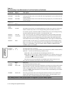
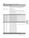
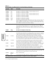
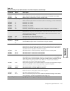
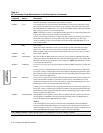
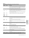
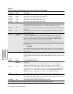
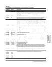
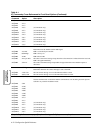
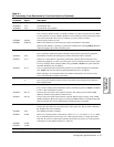
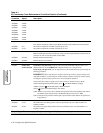
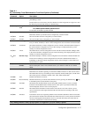
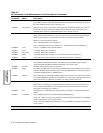
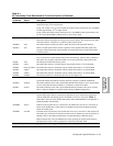
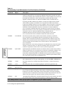
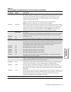
Table A-1.
AT Commands, Cross-Referenced to Front Panel Options (Continued)
AT
Command
Parameter &
Option Description
Gray shading indicates country-specific options. See Appendix C for your country’s options.