


A-44 Configuration Quick Reference
Configuration
Quick-Reference
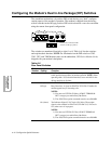
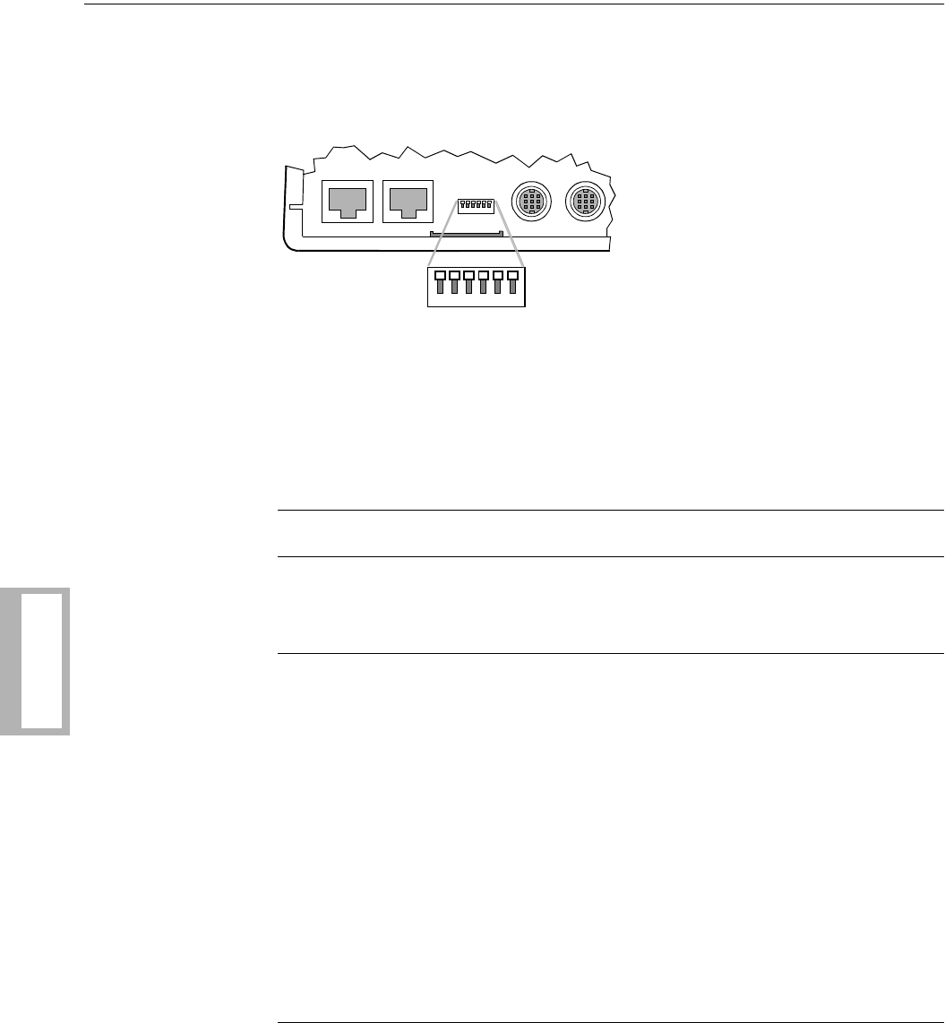
Configuring the Modem’s Dual In-line Package (DIP) Switches
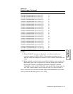
The standalone modem has a 6-position DIP switch that lets you “hard” configure
certain aspects of the modem’s operation. The modem is shipped from the factory
with all switches in the Off (up) position. DIP switch selections cannot be overridden
using the remote front panel configuration.
The switches are numbered from left to right (1 to 6). Tabl eA-6 lists the switches
and explains their function. NOTE: For information on the DIP switch on 3262,
3263, 3267, and 3268 Modem cards, see the addendum, 326X Series Modem Cards,
shipped with your modem’s backplane.
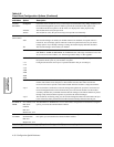
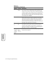
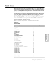
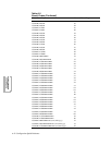
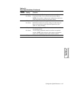
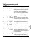
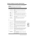
Table A-6.
Rear Panel Switches
Switch
Number Setting Function
1 Off (up) EIA/TIA 232-D Pin 23 is set for data rate input. Setting Switch 1
to this position has no effect on modem operation. NOTE: When
operating with a V.35 electrical interface, leave switch S1 in the
off (up) position at all times.
2 On (down) EIA/TIA 232-D Pin 23 is set as a data indicator.
Off (up) Busy Out select. A signal on EIA/TIA 232-D Pin 25 makes the
modem appear busy to incoming calls.
NOTES:
1) You must set DTE Pin 25=Busy (AT
*
LT, TERMINAL
OPT’s category) to enable Busy Out Select.
2) The AT&J Telco option command must be set to RJ4MB.
On (down) Test Indicator Signal (V.24 Circuit 142) Select. The modem
signals to the terminal on EIA/TIA 232-D Pin 25 (V.24 Circuit
142) when a test is in progress.
NOTES:
1) You must set DTE Pin 25=Test (AT
*
LT, TERMINAL
OPT’s category) to enable Busy Out Select.
2) The AT&J Telco option command must be set to RJ4MB.
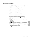
123456
PHONE
DIAL
LINE
OUT IN
NC
1 ON 6
1 2 3 4 5 6
Factory Preset 6-Position DIP
switches, in Off (up) position
.