®
8
Appearance
General
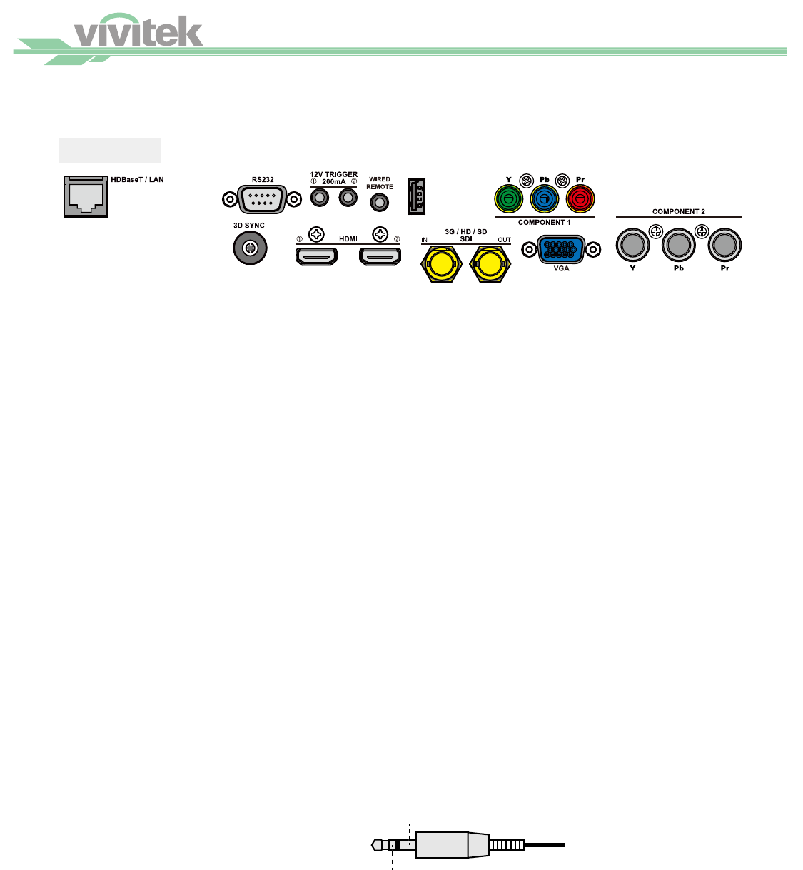
I/O Panel
USB
HDBaseT/LAN
Connect to the RJ45 Cat5 Ethernet cable.
3D Sync Out
Connect to the 3D IR synchronization signal transmitter.
HDMI
Connect to HDMI source.
3G/HD/SD SDI
Connect to SDI source.
VGA
Provide the standard 15-pin VGA connection and can connect to RGB, HD Component or personal comput-
er.
Component / Y/Pb/Rr
Connect BNC-type input terminal to the RGB or YPbPr/YCbCr output signal of video equipment.
RS-232
The 9-pin D-sub interface is used to connect to the PC control system and projector maintenance.
TRIGGER (Trigger)
The 3.5mm mini earphone jack provides 12V (+/-1.5) / 200mA Auto output for screen control.
USB
It is a port exclusively used for maintenance and only can be used by the authorized maintenance personnel.
WIRE (Wired Remote Control)
Connect to the input from the compatible IR transponder system and wired remote control.
Wire remote control
3.5mm mini jack
Tip -> Power
Ring -> Signal
Sleeve->Ground
Tip
Ring
Sleeve
Note: Please make sure the port for insertion is correct before the terminal of the wired remote control is inserted. The remote
control may be damaged if it’s inserted to the wrong port.


