


MSP430x11x1
MIXED SIGNAL MICROCONTROLLER
SLAS241C – SEPTEMBER 1999 – REVISED JUNE 2000
10
POST OFFICE BOX 655303 • DALLAS, TEXAS 75265
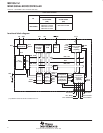
boot ROM containing bootstrap loader (continued)
features of the bootstrap loader are:
UART communication protocol, fixed to 9600 baud
Port pin P1.1 for transmit, P2.2 for receive
TI standard serial protocol definition
Implemented in flash memory version only
Program execution starts with the user vector at 0FFFEh or with the bootstrap loader (start vector is at
address 0C00h)
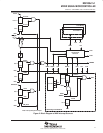
hardware resources used for serial input/output:
Pins P1.1 and P2.2 for serial data transmission
Test and RST/NMI to start program execution at the reset or bootstrap loader vector
Basic clock module: Rsel=5, DCO=4, MOD=0, DCOCLK for MCLK and SMCLK, clock divider for MCLK
and SMCLK at default: dividing by 1
Timer_A: Timer_A operates in continuous mode with MCLK source selected, input divider set to 1,
using CCR0, and polling of CCIFG0.
WDT: Watchdog timer is halted
Interrupt: GIE=0, NMIIE=0, OFIFG=0, ACCVIFG=0
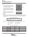
Memory allocation and stack pointer:
If the stack pointer points to RAM addresses above 0220h, 6 bytes of the stack are allocated
plus RAM addresses 0200h to 0219h. Otherwise the stack pointer is set to 0220h and allocates
RAM from 0200h to 021Fh.
NOTE:
When writing RAM data via bootstrap loader, take care that the stack is outside the range
of the data being written.
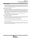
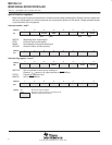
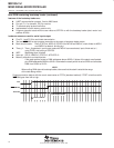
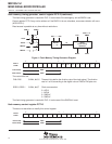
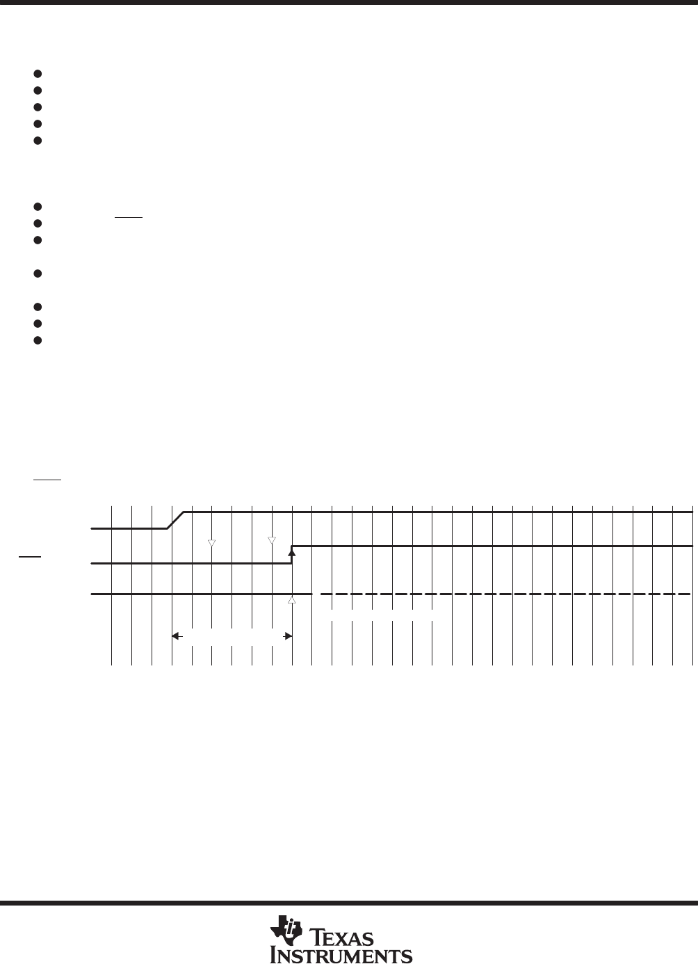
Program execution begins with the user’s reset vector at FFFEh (standard method) if TEST is held low while
RST
/NMI goes from low to high:
RST/NMI PIN
TEST PIN
User Program Starts
V
CC
Reset Condition