


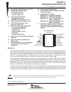
MSP430x11x1
MIXED SIGNAL MICROCONTROLLER
SLAS241C – SEPTEMBER 1999 – REVISED JUNE 2000
5
POST OFFICE BOX 655303 • DALLAS, TEXAS 75265
instruction set (continued)
Computed branches (BR) and subroutine calls (CALL) instructions use the same addressing modes as the other
instructions. These addressing modes provide
indirect
addressing, ideally suited for computed branches and
calls. The full use of this programming capability permits a program structure different from conventional 8- and
16-bit controllers. For example, numerous routines can easily be designed to deal with pointers and stacks
instead of using flag type programs for flow control.
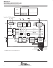
operation modes and interrupts
The MSP430 operating modes support various advanced requirements for ultralow-power and ultralow energy
consumption. This is achieved by the intelligent management of the operations during the different module
operation modes and CPU states. The advanced requirements are fully supported during interrupt event
handling. An interrupt event awakens the system from each of the various operating modes and returns with
the
RETI
instruction to the mode that was selected before the interrupt event. The different requirements of the
CPU and modules, which are driven by system cost and current consumption objectives, necessitate the use
of different clock signals:
Auxiliary clock ACLK (from LFXT1CLK/crystal’s frequency), used by the peripheral modules
Main system clock MCLK, used by the CPU and system
Subsystem clock SMCLK, used by the peripheral modules
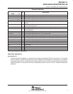
low-power consumption capabilities
The various operating modes are controlled by the software through controlling the operation of the internal
clock system. This clock system provides many combinations of hardware and software capabilities to run the
application with the lowest power consumption and with optimized system costs:
Use the internal clock (DCO) generator without any external components.
Select an external crystal or ceramic resonator for lowest frequency or cost.
Select and activate the proper clock signals (LFXT1CLK and/or DCOCLK) and clock pre-divider function.
Apply an external clock source.
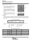
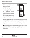
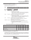
Four of the control bits that influence the operation of the clock system and support fast turnon from low power
operating modes are located in the status register SR. The four bits that control the CPU and the system clock
generator are SCG1, SCG0, OscOff, and CPUOff: