


MSP430x11x1
MIXED SIGNAL MICROCONTROLLER
SLAS241C – SEPTEMBER 1999 – REVISED JUNE 2000
16
POST OFFICE BOX 655303 • DALLAS, TEXAS 75265
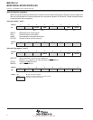
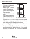
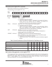
flash memory control register FCTL3 (continued)
LOCK 012Ch, bit4,
The lock bit may be set during any write, segment-erase, or
mass
-erase request.
Any active sequence in progress is completed normally. In segment-write mode,
the SEGWRT bit is reset and the WAIT bit is set after the mode ends. The lock
bit is controlled by software or hardware. If an access violation occurs and the
ACCVIFG is set, the LOCK bit is set automatically.
0: Flash memory may be read, programmed, erased, or
mass
erased.
1: Flash memory may be read but not programmed, erased, or
mass
erased.
A current program, erase, or
mass
-erase operation will complete normally.
The access-violation interrupt flag ACCVIFG is set when data are written to
the flash memory module while the lock bit is set.
EMEX, 012Ch, bit5,
Emergency exit. The emergency exit should only be used if the flash memory
write or erase operation is out of control.
0: No function.
1: Stops the active operation immediately, and shuts down all internal parts in
the flash memory controller. Current consumption immediately drops back
to the active mode. All bits in control register FCTL1 are reset. Since the
EMEX bit is automatically reset by hardware, the software always reads
EMEX as 0.
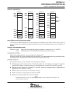
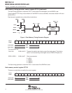
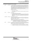
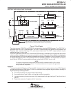
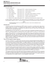
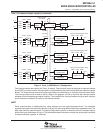
flash memory, interrupt and security key violation
One NMI vector is used for three NMI events: RST/NMI (NMIIFG), oscillator fault (OFIFG), and flash-memory
access violation (ACCVIFG). The software can determine the source of the interrupt request since all flags
remain set until they are reset by software. The enable flag(s) should be set simultaneously with one instruction
before the return-from-interrupt RETI instruction. This ensures that the stack remains under control. A pending
NMI interrupt request will not increase stack demand unnecessarily.