


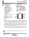

MSP430x11x1
MIXED SIGNAL MICROCONTROLLER
SLAS241C – SEPTEMBER 1999 – REVISED JUNE 2000
7
POST OFFICE BOX 655303 • DALLAS, TEXAS 75265
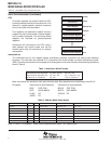
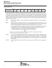
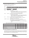
interrupt vector addresses
The interrupt vectors and the power-up starting address are located in the memory with an address range of
0FFFFh-0FFE0h. The vector contains the 16-bit address of the appropriate interrupt handler instruction
sequence.
INTERRUPT SOURCE INTERRUPT FLAG SYSTEM INTERRUPT WORD ADDRESS PRIORITY
Power-up, external reset, watchdog
WDTIFG (Note1)
KEYV (Note 1)
Reset 0FFFEh 15, highest
NMI, oscillator fault, flash memory
access violation
NMIIFG (Notes 1 and 4)
OFIFG (Notes 1 and 4)
ACCVIFG (Notes 1 and 4)
(non)-maskable,
(non)-maskable,
(non)-maskable
0FFFCh 14
0FFFAh 13
0FFF8h 12
Comparator_A CAIFG maskable 0FFF6h 11
Watchdog timer WDTIFG maskable 0FFF4h 10
Timer_A CCIFG0 (Note 2) maskable 0FFF2h 9
Timer_A
CCIFG1, CCIFG2, TAIFG
(Notes 1 and 2)
maskable 0FFF0h 8
0FFEEh 7
0FFECh 6
0FFEAh 5
0FFE8h 4
I/O Port P2 (eight flags – see Note 3)
P2IFG.0 to P2IFG.7
(Notes 1 and 2)
maskable 0FFE6h 3
I/O Port P1 (eight flags)
P1IFG.0 to P1IFG.7
(Notes 1 and 2)
maskable 0FFE4h 2
0FFE2h 1
0FFE0h 0, lowest
NOTES: 1. Multiple source flags
2. Interrupt flags are located in the module
3. There are eight Port P2 interrupt flags, but only six Port P2 I/O pins (P2.0–5) are implemented on the 11x1 devices.
4. (non)-maskable: the individual interrupt enable bit can disable an interrupt event, but the general interrupt enable cannot.
Nonmaskable: neither the individual nor the general interrupt enable bit will disable an interrupt event.