


TPS56xx Functions
2-7
Design Procedure
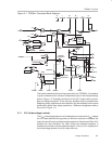
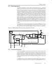
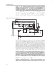
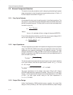
2.1.5 Noise Suppression
Hysteretic regulators, by nature, have a fast response time to V
O
transients
and are thus inherently noise sensitive due to the very high bandwidth of the
controller. Noise suppression circuits were added to the TPS56xx to improve
the noise immunity, as shown in Figure 2–2. Internal low-pass filters with a pole
frequency of 5 MHz were added to the inputs of the hysteretic comparator.
These low-pass filters are referenced to the same analog ground as the
hysteretic comparator. There is a common-mode filter with a 4-MHz pole
between VREFB and VHYST to filter out noise between these pins. A double
pulse suppression circuit prohibits spurious pulses from propagating to the
gate drivers. The double pulse suppression circuit becomes active when the
comparator has toggled or when the LOHIB pin (which is connected to the
power MOSFETs) has transitioned, providing additional noise immunity from
internally and externally generated noise. The suppression circuit is active for
150 ns.
A low-pass filter is recommended between V
O
and the VSENSE pin (R1 and
C3 in Figure 2–2); recommended values are 100 ohms and 1 nF. This low-pass
filter is included in the evaluation design of Figure 1–3 (R8, R11, and C20).
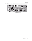
Figure 2–2. Block Diagram Showing Noise Suppression Circuits
Adaptive
Deadtime
Control
HIGHDR
C1
L1
V
in
L2
C2
LOHIB
LOWDR
V
phase
VO
TPS56xx Synchronous-Buck Controller
C3R2
Hysteresis
Setting
VSENSE
R1
VHYST
+–
VREFB
R3
R4
R5
R6
Reference
V
ref
IOUT
VH_SET
Double Pulse
Suppression
Circuit
5 MHz
Filter
5 MHz
Filter
4 MHz
Filter
V
ds
Sensing
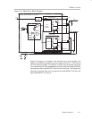
2.1.6 Overcurrent Protection
Overcurrent protection is provided by measuring the on-state voltage of the
high-side MOSFET, conditioning the measured voltage, and comparing the
result to a reference voltage. If the output current exceeds the current limit
setpoint, a fault latch is set and the output drivers are turned off. Vcc (12 V)
must be reduced to below the undervoltage lockout value to restart the
converter.
A sample-and-hold circuit measures the power supply output current by
sensing the on-state drain-to-source voltage of the high-side MOSFET (Q1 in