Test Summary
3-3
Test Results
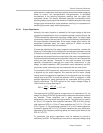
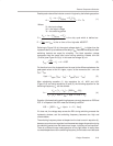
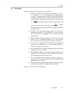
in a linear fashion. There is no discernable overshoot in the waveforms. In this
application, output voltage rise time is set to approximately 9 mS with an
external capacitor. Although the EVMs have been tested with a very short Vcc
rise time, (see Figures 3–26 and 3–35) it is recommended to keep the rise time
of Vcc longer than 3mS as shown in Figures 3–8 and 3–17.
3.1.5 Frequency Variation
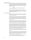
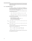
The switching frequency for a hysteretic controller depends on the input and
output voltages and the output filter characteristics. It has approximately the
same frequency variation as constant OFF time controllers. The precise
equation for switching frequency, confirmed by experiment, is presented in TI’s
application report
Designing Fast Response Synchronous Buck Converters
Using the TPS5210
and in the paper, represented at HFPC–98
A Fast,
Efficient Synchronous-Buck Controller for Microprocessor Power Supplies
http://www.ti.com/sc/docs/msp/papers/index.htm.
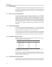
The frequency variation over all input voltage and output current combinations
is presented in the following table.
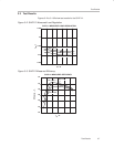
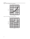
Switching frequency graphs versus load at different line voltages are shown
in Figures 3–5, 3–14, 3–23, and 3–32.
Evaluation Board
Frequency Variation,
(kHz)
SLVP111, 3.3 V 97–175
SLVP112, 2.5 V 189–247
SLVP113, 1.8 V 262–312
SLVP114, 1.5 V
296–378
3.1.6 Load Current Transient Response
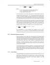
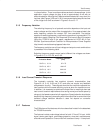
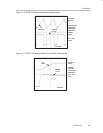
The hysteretic controller has excellent dynamic characteristics (see
Figures 3–10, 3–19, 3–28 and 3–37) and does not require any feedback
compensation circuitry. These figures show that the
controller
responds to a
load transient within the same switching cycle as when the transient occurs.
In addition, it is necessary to optimize the output filter to meet high slew-rate
load current transient requirements thus saving money and board space by
using only the fewest expensive bulk capacitors. Special attention should also
be paid to high frequency decoupling within the output filter to control the initial
transient voltage deviation because it does not depend on controller
characteristics.
3.1.7 Features
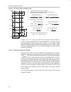
The EVMs have all the features, which are described in detail in the datasheet
for TPS56XX controller.
The features include undervoltage lockout for both 12 V and 5 V input, inhibit
signal, power good signal, overvoltage protection, slow start, remote sense,
and overcurrent protection. Overcurrent limit is set to an 8 amp – 10 amp level.


