


www.ti.com
2BoardLevelDescription
2.1TestPointsandJumpers
BoardLevelDescription
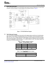
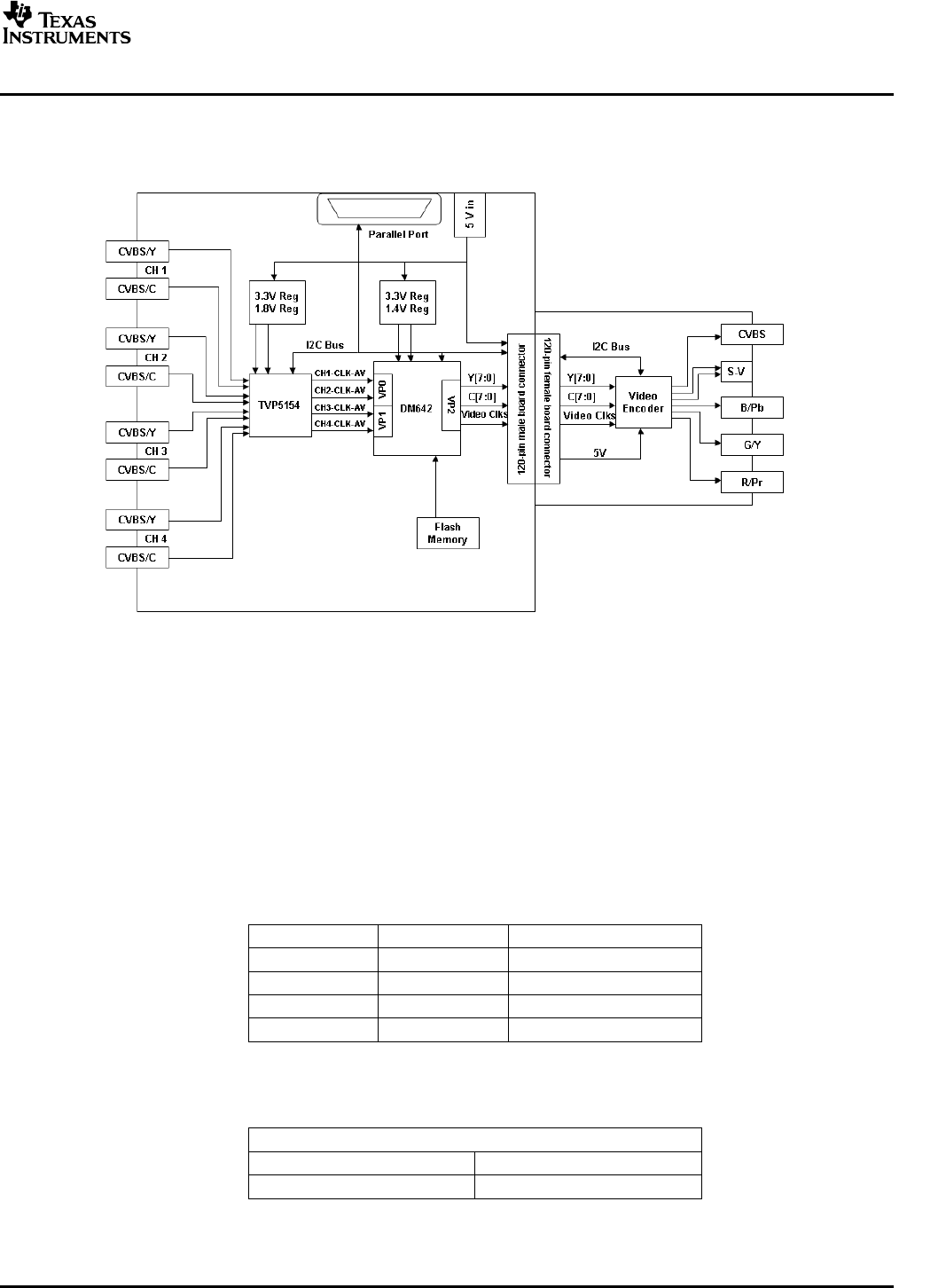
TheTVP5154EVMconsistsoftheTVP5154EVMmoduleandtheencoderEVMmodule.A4-row120-pin
connectorconnectstheboards.TheblockdiagramoftheEVMsetisshowninFigure1.
Figure1.TVP5154EVMBlockDiagram
TheTVP5154EVMwasdesignedwithtestpointsandjumperstohelpinevaluationandtroubleshooting.
EachjumperissetbydefaultinitspreferredstatefortheTVP5154EVM.TherearetestpointsforSCL,
SDA,3.3V,and1.8V.Alldigitalvideodataforeachdecodercorearebroughtouttoadual-rowheader,
whichallowseasyhookuptotestequipment.TheI
2
Caddressselectionismadewithtwoshuntjumpers,
whichareonlyreadafteraresetoratpowerup.Thedefaultaddressis0xB8.Iftheaddressneedstobe
changed,theTVP5154mustreceiveareset.
Table1.I
2
CAddressSelectionJumpers
(I2CSEL1,JP9andI2CSEL2,JP10)
JP9JP10I
2
CADDRESS
2-32-30xB8
1-22-30xBA
2-31-20xBC
1-01-20xBE
Table2.Power-Down-ModeSelectionJumper
(PDN,JP11)
PWDN
1-2Normaloperation
2-3Powerdown
SLEU069A–February2006–RevisedJuly2006TVP5154EVMUser'sGuide7
SubmitDocumentationFeedback