


www.ti.com
3System-LevelDescription
4RequiredHardwareandEquipment
5HardwareSetup
System-LevelDescription
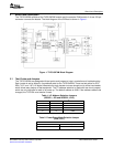
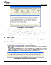
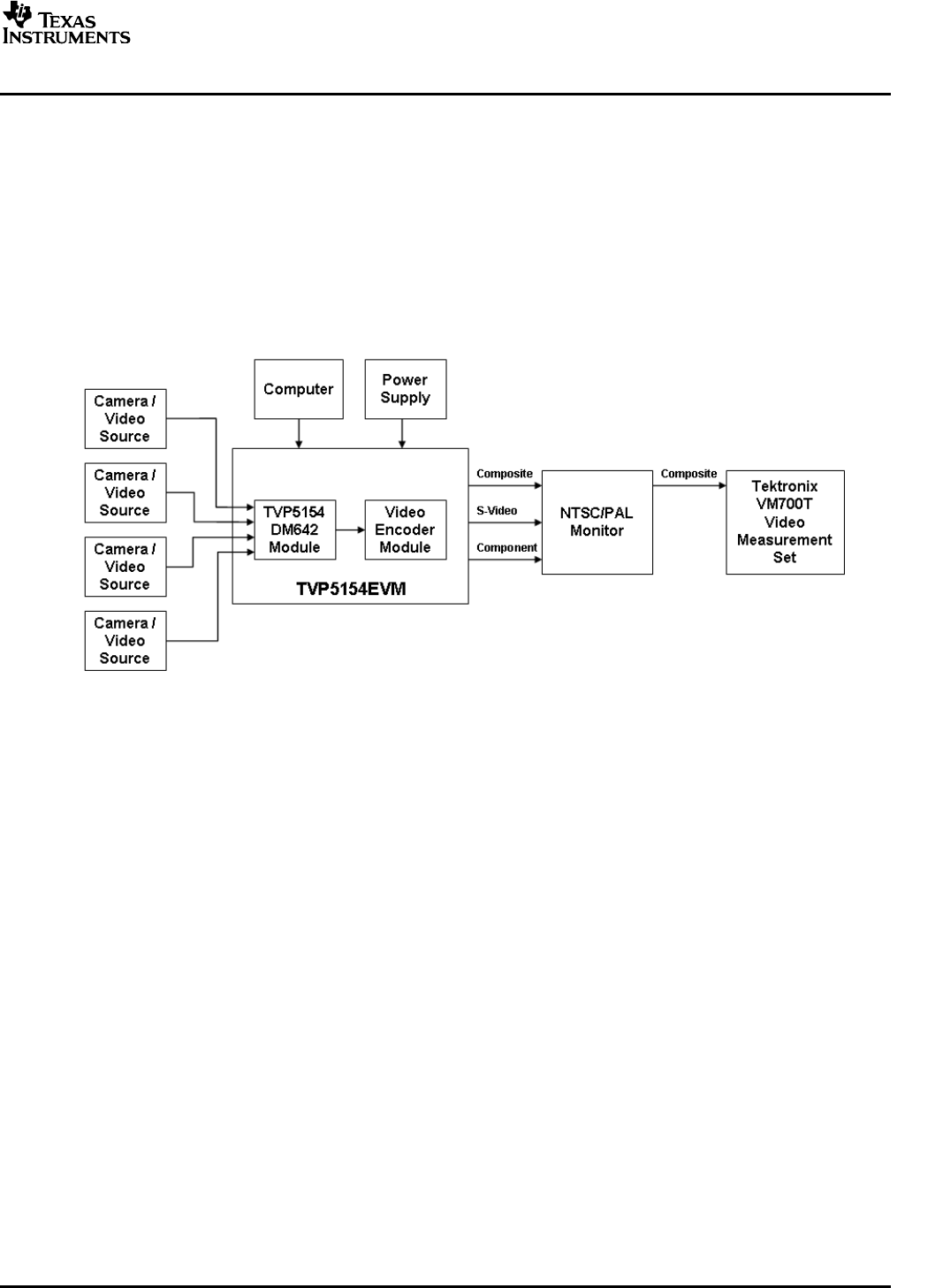
Asystem-levelblockdiagramincorporatingtheTVP5154isshowninFigure3.Typical
commercially-availabletestequipmentisalsoshown.Theprimaryfeaturesofthisconfigurationare:
•Powerisprovidedbyasingle5-VpowersupplyprovidedwiththeEVMandissharedbetweenboth
modulesviathe120-pinconnector.
•SupportedanaloginputsincludecompositevideoandS-video.
•Re-encodedcompositevideoandS-videoareoutputviatheencodermodule.
•Component(YPbPr)videoisoutputviatheencodermodule.
•I
2
CbusinitializesthevideodevicesviaaPCparallelport.
•TheTVP5154videodecoderperformanceparametersmaybemeasuredwithavideoanalyzer.
Figure3.TVP5154EVMSystem-LevelBlockDiagram
TherequiredhardwareandequipmentnecessarytousetheTVP5154EVMare:
•TVP5154EVM(provided)
•Universal5-Vpowersupply(provided)
•Parallelcable(provided)
•Windows-basedPCwithCD-ROMdriveandWin95™orlater
•CompositeorS-videocablesforinputs
•Composite,S-video,orcomponentcableforoutput
•Videosources(securitycamera,patterngenerator,Quantumgenerator,DVDplayer,etc.)
•Displaymonitorthatsupportscomposite,S-video,orcomponentvideoinput
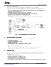
Figure1showstheTVP5154EVMlayoutandindicatesthelocationofthepowersupplyandthe
appropriateconnectors.Allconnectorsarelabeledaccordingtotheirfunction.TopreparetheEVMfor
evaluation,connectthefollowing:
1.TVP5154moduletoencodermodule
2.ParallelportcablefromTVP5154EVMtothePC
3.AnalogvideosourcestoTVP5154EVMinputs
4.AnalogvideooutfromTVP5154EVMtomonitor
5.5-VpowersupplytothedcjackontheTVP5154board.AgreenLEDoneachboardshouldnowbelit.
SLEU069A–February2006–RevisedJuly2006TVP5154EVMUser'sGuide9
SubmitDocumentationFeedback