


19
4300 Series Ancillary Cabinets Installation and Operation Manual
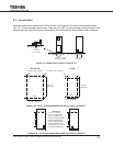
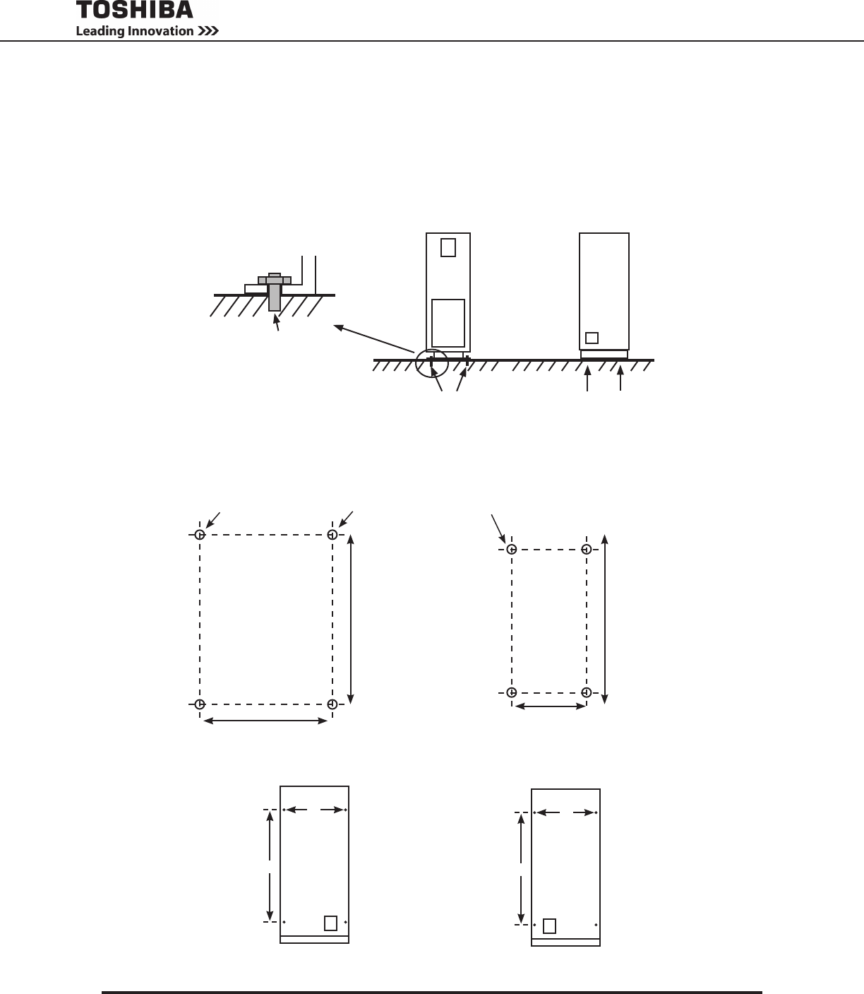
8.3 Anchor Bolts
InstalltheanchorboltstosecuretheUPSontheoor.SeeFigure8.2foranchorboltinstallationdetail.
Use 1/2” (12 mm) diameter anchor bolts. There are four 0.63” (16 mm) diameter holes provided in the
cabinetbase.SeeFigure8.3AfortheholelocationsanddimensionsforthespeciedAncillaryCabinets..
Anchor Bolt
(1/2 in (12 MM))
4 x 0.63 in. (16 mm)
diameter bolt holes
4 bolt holes
(Side View)
FIGURE 8.2 ANCHOR BOLT INSTALLATION DETAIL
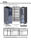
FIGURE 8.3A HOLE LOCATIONS/DIMENSIONS ON BOTTOM OF CABINETS
431A/431B
Back
Front
4 x 0.63 in. Dia. (16 mm)
19.0 in. (483 mm)
26.7 in..
(677 mm)
431M
Back
Front
11.0 in. (279 mm)
20.0 in.
(508 mm)
4 x 0.63 in. Dia. (16 mm)
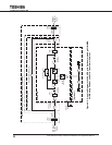
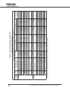
FIGURE 8.3B HOLE LOCATIONS/DIMENSIONS ON SIDES OF CABINETS
A
B
Left Side
A
B
Right Side
Dimensions
A - 29 in. (736 mm)
B - 60 in. (1523 mm)
Use 4 ea. 3/8”x16 2 in
long bolts to join adjacent
UPS /ancillary cabinet
frames. (The left side
of each cabinet has a
3/8”x16 pin nut to receive
the corresponding bolt.)