


51
4300 Series Ancillary Cabinets Installation and Operation Manual
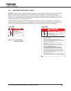
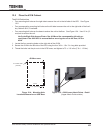
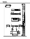
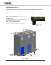
STEP 2: Slide Side Plates in along C-Channel base.
2.1 Facing the front of the UPS, slide a side kick plate with the smooth side facing out down along the left base C-
channel skid until it is protruding about one inch in front of the UPS. See Figure 13-2.
2.2 Repeat for the right C-channel skid.
STEP 3: Align the F/B Plate with the UPS front.
PlaceaF/BkickplateontheoorasinStep13-1.AngletherightedgeoutawayfromtheUPSuntilthepairoffront
slots at the ends of the F/B kick plate are visible. See Figure 13-3.
STEP 4: Insert Side Plate tabs into F/B Plate slots.
InsertthesideplatetabsintotheF/BkickplateslotsontheoorinfrontoftheUPS,andthenslidetherightedgeout
until the pair of front slots at each end of the plate are visible. See Figure 13-3.
4.1 Carefully slide the F/B kick plate forward until the Side plate tabs are inserted in the F/B kick plate slots. (NOTE
- This is a snug t.)
4.2 Slide the right side of the F/B kick plate forward to engage the tabs of the right Side kick plate.
4.3 Slide the F/B kick plate forward until the left and right Side kick plate magnetic latches make contact with the
F/B kick plate.
4.4 Slide the F/B kick plate back until it make contact with both the C-channel base skids.
STEP 5: Attach the rear F/B Plate to the back of the UPS
Repeat Step 4 for the F/B kick plate at the rear of the UPS.