


34
4300 Series Ancillary Cabinets Installation and Operation Manual
Ilsco P/N Description Conductor Size Fitting Color
CLND-4/0-12-134
CSWD -4/0-12-134
Long Barrel
Short Barrel
4/0 Purple
CLND-250-12-134
CSWD -250-12-134
Long Barrel
Short Barrel
250 Yellow
CLND-300-12-134
CSWD -300-12-134
Long Barrel
Short Barrel
300 White
CLND-350-12-134
CSWD -350-12-134
Long Barrel
Short Barrel
350 Red
Go to Section Place the 431B Cabinet.
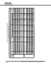
Table 11.3 - 431B Power Cable Sizes
(Cable sizes for 75°C Copper Cable)
Recommended/Maximum Wire size and Torque Requirement
UPS
Rating
Maximum DC Current Recommended Cable
Sizes
UPS Terminal Lug
Tightening Torque
431B Bus Lugs
Tightening Torque
20 kVA 84 Adc
4 AWG – 350 kcmil 200 in.-lbs. 119ft-lb(161N•M)
30 kVA 126 Adc
1 AWG – 350 kcmil 200 in.-lbs. 119ft-lb(161N•M)
40 kVA 169 Adc
1/0 – 350 kcmil 200 in.-lbs. 119ft-lb(161N•M)
50 kVA 210 Adc
4/0 – 350 kcmil 200 in.-lbs. 119ft-lb(161N•M)
60 kVA 253 Adc
250 kcmil – 350 kcmil 200 in.-lbs. 119ft-lb(161N•M)
* Wire capacity for DC lugs is 350 kcmil - 6 AWG,
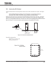
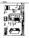
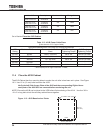
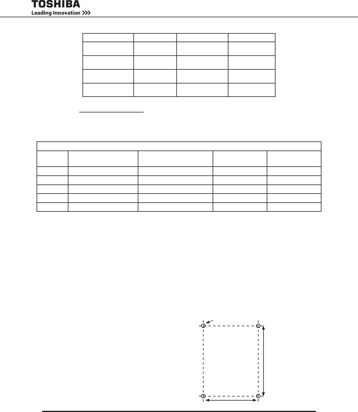
11.4 Place the 431B Cabinet
The 431B Cabinet has four mounting holes to anchor the unit after is has been set in place. See Figure
10-3. Use 1/2 in (12 mm) bolts to anchor the 431B.
Verify the Left Side Access Plate of the 431B and the corresponding Right side ac-
cess plate of the 4300 UPS are removed before anchoring the unit.
NOTE:Ensurethe431BcanbejoinedtotheUPSbeforenalanchoringofthe431A.Usefour3/8in.
-16 x 2 in long bolts to bolt the ancillary cabinet frames together.
Back
Front
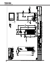
4 x 0.63 in. Dia. (16 mm)
19.0 in. (483 mm)
26.7 in..
(677 mm)
Figure 11-3 - 431B Base Anchor Points