


53
4300 Series Ancillary Cabinets Installation and Operation Manual
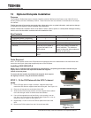
Installing 4300-30/50-KP-B
The 4300-30/50-KP-B Kick Plate Kit contains one pair of F/B kick plates. This kit is required for each standard ad-
ditional 4300 Series add on frame, such as the 431A and 431B. The 431M is already provided with a base skirt.
NOTE: Due to variations within manufacturing specications, the spacing on the base channels may be
slightly greater of less than the separation between the magnetic latches of the kick plates.
To correct this the installer should bend the magnetic latch support tab slightly to ensure a snug t to the
base channels.
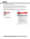
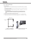
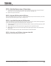
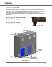
STEP 1: Move Side Plates to outer-most
C-channel base
Move the Side kick plates to the the outer sides of the assembled
4300 Series units. See Figure 13-7, 13-8.
STEP 2: Install the F/B Plates
Install the F/B kick plates as described on Pages 50-52.
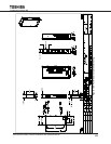
Figure 13-7
4300 UPS
Aux. Cabinet
MBS Cabinet
Batt. Cabinet
Figure 13-8
Side Kick
Plate
F/B Kick Plates
(Back Side Similar)
Side Kick
Plate