


50
4300 Series Ancillary Cabinets Installation and Operation Manual
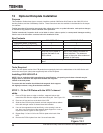
13 Optional Kickplate Installation
Purpose
This Installation Guide shows how to correctly install the optional 4300 Series Kick Plates on the 4300 UPS, 431A
Ancillary Cabinet, and the 431B Battery Cabinet. These instructions are also available in the Manuals for the respec-
tive cabinets.
Toshiba International Corporation reserves the right, without prior notice, to update information, make product changes,
ordiscontinueanyproductorserviceidentiedinthispublication.
Toshiba International Corporation shall not be liable for direct, indirect, special, or consequential damages resulting
from the use of the information contained within this Installation Guide.
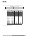
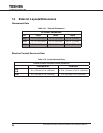
Box Contents
Part Number 4300-30/50-KP-A 4300-30/50-KP-B
Instruction Sheet (P/N 66597) 1 1
F/B (Front/Back) Kick Plate, 22 in. 2 2
Side Kick Plate, 30.5 in. 2 (None)
NOTES Initial set of kick plates to
enclose the base of one
4300 cabinet.
Add-on kick plates to enclose ad-
ditional cabinets. The sides are
moved to the outer sides outermost
cabinets in the lineup.
Both pair of kick plates are symmetrical - there is no upside
down.
Tools Required
None - The kick plates consist of the F/B panels that magnetically latch to the welded base of the 4300 Series cabi-
nets and a second pair (sides) that magnetically latch to the F/B plates.
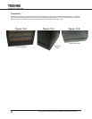
Installing 4300-30/50-KP-A
NOTE: Due to variations within manufacturing specications, the spacing on the base channels may be
slightly more or less than the separation between the magnetic
latches of the kick plates.
To correct this the installer should bend the magnetic latch support
tab slightly to ensure a snug t to the base channels.
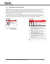
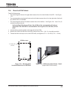
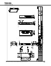
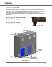
STEP 1: Fit the F/B Plates with the UPS C-channel
skids.
1.1 PlaceaF/Bkickplateonedgeontheoor,magneticlatchesside
toward the UPS with the magnetic latch faces facing left. See Figure 13-1.
1.2 Place one in front and one at the back of the UPS.
1.3 Slide the front F/B kick plate forward until both magnet latches adhere
to the left and right vertical C-channel base skid member.
1.4 Ifoneofthemagnetsdoesnotlatchrmly,orthespacingistoonar-
row, bend one or the other of the magnetic latch supports in or out as
requiredtoensureagoodt.SeeFigure13-1.
1.5 Repeat Step 13-3 and 13-4 for the F/B kick plate at the back of the
UPS.
1.6 Remove the F/B kick plates from the C-channel base skids.
Left Base Skid
Figure 13-1
Right Base Skid