


45
4300 Series Ancillary Cabinets Installation and Operation Manual
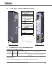
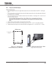
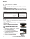
12.5 Place the 431M Cabinet
The 431M Cabinet has
• Four mounting bolt holes on the right side to secure the unit to the left side of the UPS. See Figure
12-5.
• Four corresponding mounting bolt holes on the left side to secure the unit to the right side of the Auxil-
iary Cabinet 431A, if available.
• Fourmountingboltholesonthebasetoanchortheunittotheoor.SeeFigure12.4.Use1/2in(12
mm) bolt to anchor the unit.
Verify the Right Side Access Plate of the 431M and the corresponding left side ac-
cess plate of the 4300 UPS is removed before securing the unit to the oor, UPS or
431A.
1. Locate the four mounting holes on the right side of the 431M.
2. Secure the 431M to the left side of the UPS using the four 3/8 in. -16 x 2 in. long bolts provided.
3. Thread the bolts into the pin-nuts in the UPS frame, and tighten to 70 +/- 10 in-lbs (7.9 +/- 1.2 Nm).
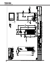
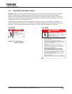
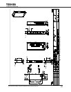
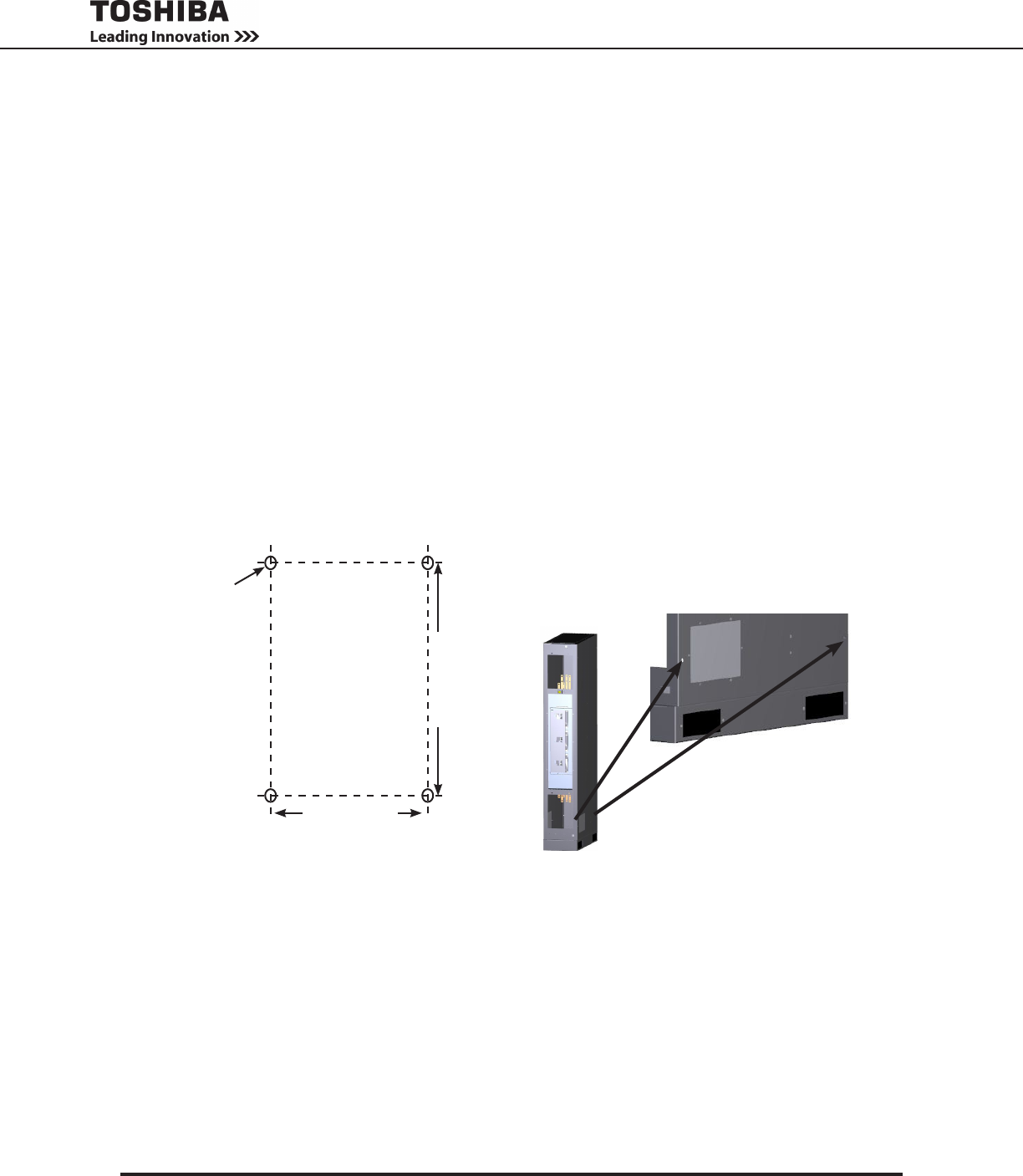
Figure 12-4 - Mounting Hole
Locations/Dimension on UPS Base
431Mxxx-xxxx
Back
Front
11 in. (280 mm)
20 in. (508 mm)
4 x 0.63 in. Dia.
(16 mm)
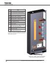
Figure 12-5 - 431M Lower Attach Points - Detail
(Upper Attach Points similar)