


23
4300 Series Ancillary Cabinets Installation and Operation Manual
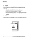
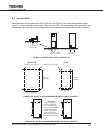
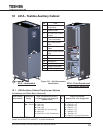
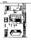
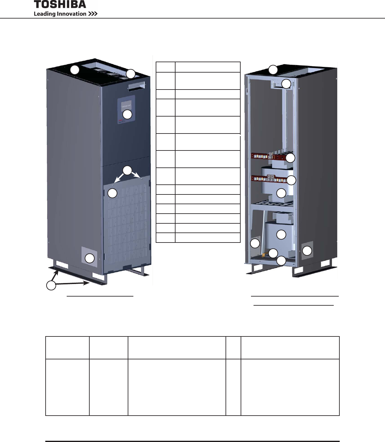
10 431A - Toshiba Auxiliary Cabinet
No. Part
1 Fan Module (Hot
Swappable)
2 Toshiba Label
3 Air Filter Grill Thumb
Screws
4 Air Filter Grill
(Front Accessible)
5 Top Cable Access
Plate
6 Side Cable Access
Plates
7 Bottom Cable Access
Plate
8 TB-2
9 TB-1
10 Ground Bus
11 Input Transformer
12 Output transformer
13 Forklift Lifting Points
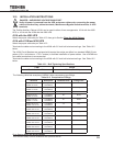
10.1 4300 Auxiliary Cabinet Transformer Options
(All cabinets are O’Brien Black (Textured))
Xfmr Cabinet
Part Number*
Transformer
Rating
Input Transformer(s) Primary
and Secondary Line Voltage IN,
208/120 V OUT
# of
Φ
Output Transformer
208/120 V IN, Load Voltage OUT
431A- 300 – 30 kVA
500 – 50 kVA
Where line voltage is :
B–208V(Δ)
C–240V(Δ)
M–600V(Δ)
N–380/400/415V(Δ)(multi-tap)
S–480V(Δ)
X – 208/120 V (Y) (No Transformer)
3 Where load voltage is :
H – 220/127 V (Y)
J – 240/138 V (Y)
K – 480/277 V (Y)
M – 600/347 V (Y)
P – 380/220 V (Y)
Q – 400/230 V (Y)
X – 208/120 V (Y) (No Transformer)
Example: 431A500S3K is a 50kVA, three-phase transformer cabinet with a 480V to 208/120V input trans-
former, and a 208/120 V to 480/277 V output transformer.
431A - Assembled 431A - Front Panels and
Dead Fronts Removed
Figure 10-1 - 431A Component
Identication
7
5
8
10
11
12
1
9
6
6
4
6
3
2
5
13
1