


36
4300 Series Ancillary Cabinets Installation and Operation Manual
431B
UPS
Power
Input/
Output
Cables
4300 Series UPS
24V DC
Supply
(PCB15)
1 2 1 2
(Battery Shunt Trip)
TB1
+ -
TB3
1 2 3 4
J4
(DC Power)
1 2 3 4
P1 P2
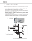
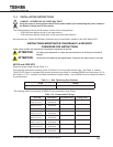
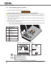
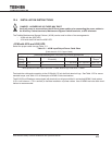
11.6 Wire the Battery Cabinet to the UPS
1. Select the DC power cables per Table 11.2 /Table 11.3.
Switch the Battery Cabinet Circuit Breakers off before removing dead fronts.
Failure to switch breakers off may result in electric shock, burns, personal injuries or UPS failure.
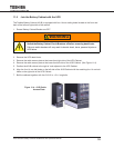
2. Run the power cables from UPS power terminals TB1 (+) and (-) to 431B Cabinet power terminals (+)
and (-) per Figure 11.5 and 11.6.
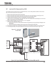
3. Select the power cables per Table 11.2 /Table 11.3. Cable size for the 431B is determined by the full
load capacity of the UPS.
4. Run the power cables from UPS power terminals TB1 (+) and (-) to 431B Cabinet power terminals (+)
and (-) per Figure 11.5 and Figure 11.6.
Note: The UPS cable ends insert into power lugs, the 431B ends require a NEMA 2-hole connec-
tor to connect to the +/- bus terminals.
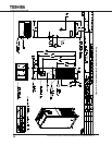
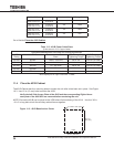
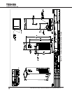
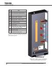
No. Component
1 Positive Terminal (+)
Bus Strip
2 Negative Terminal (-)
Bus Strip
3 Lexan Shield with
Cable Access
4 Ground Bus
5 Bottom Cable Access
Plate
6 Side Cable Access
Plate
Figure 11-5 - 431B DC Bus Terminal Detail
3
2
1
4
6
5
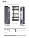
Figure 11-6 - 431B DC and Breaker Cable Connections
WARNING
TB1
AC OUT
AC IN
U V W
U V W
N +N