


27
4300 Series Ancillary Cabinets Installation and Operation Manual
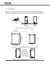
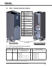
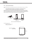
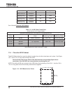
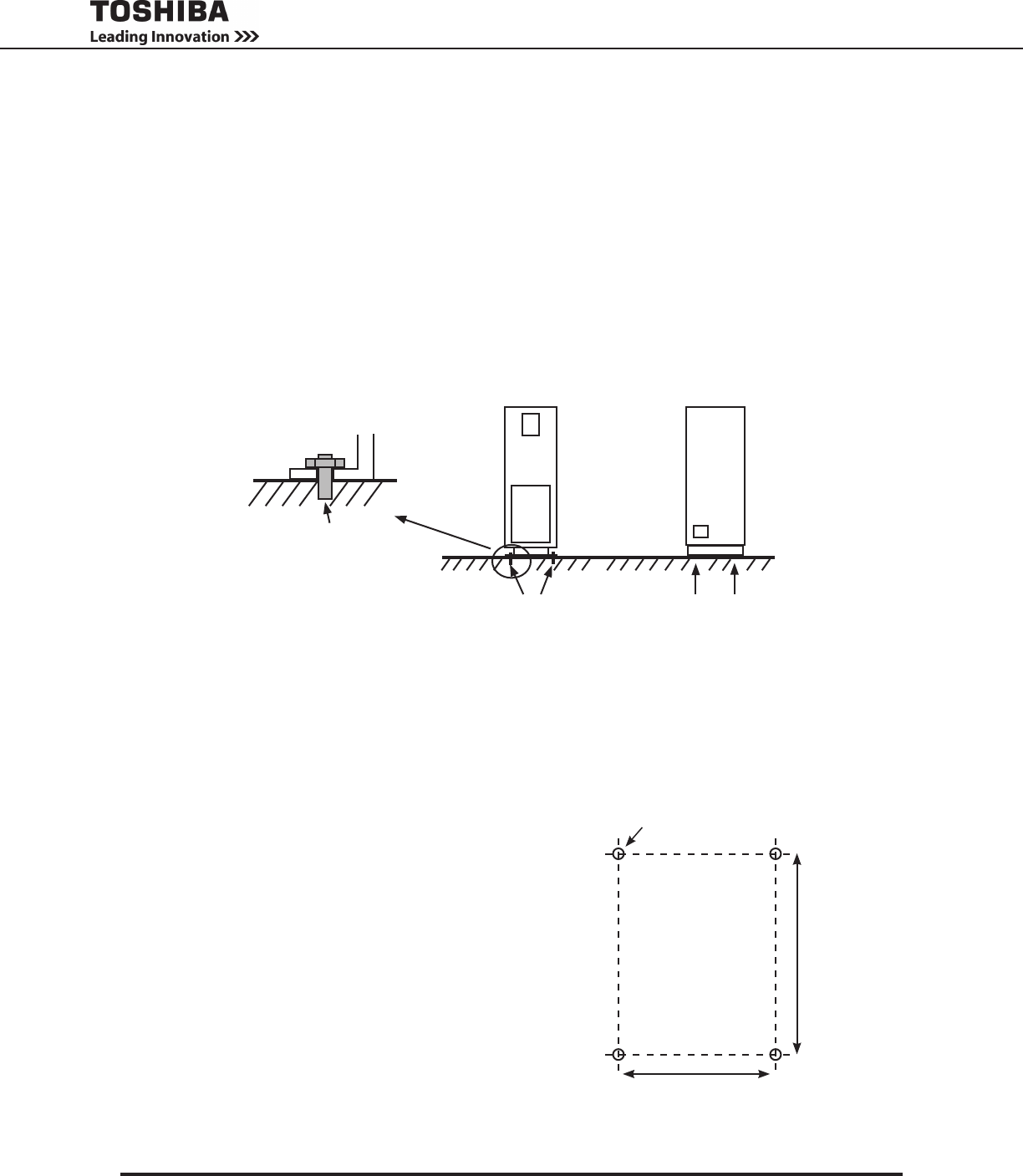
10.5 Anchor the 431A Cabinet
The 431A Cabinet has four mounting holes to anchor the unit after is has been set in place. See Figure
10-4.
Verify the Right Side Access Plate of the 431A and the corresponding left side ac-
cess plate of the 431M or 4300 UPS is removed before anchoring the unit.
NOTE:Ensurethe431AcanbejoinedtotheUPS/431Mbeforenalanchoringofthe431A.Seebelow.
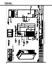
InstalltheanchorboltstosecuretheUPSontheoor.SeeFigure9-4foranchorboltinstallationdetail.
Use 1/2” (12 mm) diameter anchor bolts. There are four 0.63” (16 mm) diameter holes provided in the UPS
base.SeeFigure8.3fortheholelocationsanddimensionsforthespeciedUPSmodels
If the 431A is joining to the:
4300 UPS, go to section 10.6
431M, go to section 10.7
Back
Front
4 x 0.63 in. Dia. (16 mm)
19.0 in. (483 mm)
26.7 in..
(677 mm)
Figure 10-4 - 431A Base
Anchor Points
Anchor Bolt
(1/2 in (12 mm)
4 x 0.63 in. (16 mm)
diameter bolt holes
4 bolt holes
(Side View)
Figure 10-3 Anchor Bolt Installation Detail