


35
4300 Series Ancillary Cabinets Installation and Operation Manual
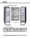
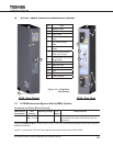
11.5 Join the Battery Cabinet with the UPS
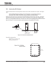
The Toshiba Battery Cabinet (431B) is equipped with four 14 mm mating holes located on the front and
back of the left and right sides of the cabinet.
1. Ensure Battery Cabinet Breaker are OFF.
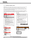
WARNING
Switch the Battery Cabinet Circuit Breakers off before removing dead fronts.
Failure to switch breakers off may result in electric shock, burns, personal injuries or
UPS failure.
2. Remove the UPS dead-fronts.
3. Remove the cable access plate at the lower-front right side of the UPS Cabinet.
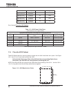
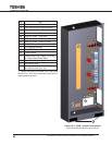
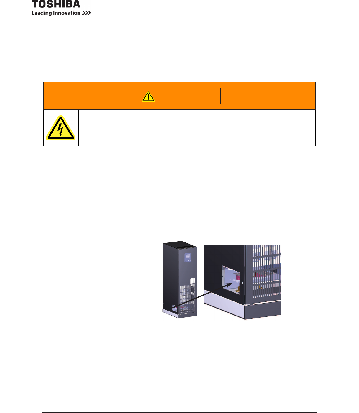
4. Remove the cable access plate at the lower-front left side of the 431B Cabinet. (See Figure 11-4)
5. Position the 431B cabinet to the right of and adjacent to the UPS Cabinet.
6. Align the four 14 mm bolt holes on the left side of the 431B Cabinet with the matching four 14 mm bolt
holes on the right side of the UPS Cabinet.
7. Bolt the cabinets together with four 3/8-16 in. x 2 in. long bolts.
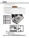
Figure 11-4 - 431B Cable
Access Plate