


E6581741
- 2 -
Table of Contents
1. OVERVIEW .................................................................................................................................................4
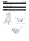
2. NAMES AND FUNCTIONS ........................................................................................................................4
2.1. Outline..................................................................................................................................................4
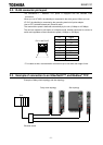
2.2. RJ45 connector pin layout ...................................................................................................................5
2.3. Example of connection to an EtherNet/IP™ and Modbus
®
TCP .........................................................5
2.4. LED indicator........................................................................................................................................6
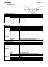
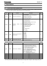
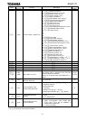
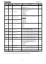
3. PARAMETERS ...........................................................................................................................................7
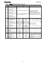
3.1. Communication parameters.................................................................................................................7
3.2. The details of the parameter setting ..................................................................................................11
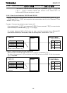
3.2.1. Device name (c081-c096).................................................................................................11
3.2.2. Assigning IP addresses (c504, c505-c516) ...............................................................12
3.2.3. Network error detection (c100 - c103, c523) ...............................................................13
3.2.4. Command data (c001-c006), Monitor data (c021-c026).........................................14
4. OBJECTS..................................................................................................................................................22
4.1. Identity Object (0x01) .........................................................................................................................23
4.2. Message Router Object (0x02) ..........................................................................................................25
4.3. Assembly Object (0x04) .....................................................................................................................26
4.4. Connection Manager Object (0x06)...................................................................................................27
4.5. Motor Data Object (0x28)...................................................................................................................28
4.6. Control Supervisor Object (0x29).......................................................................................................29
4.6.1. Run/Stop Event Matrix................................................................................................................31
4.6.2. State of the drive.........................................................................................................................31
4.6.3. Control Supervisor State Transition Diagram.............................................................................31
4.7. AC/DC Drive Object (0x2A) ...............................................................................................................32
4.8. Parameter Objects (0x64)..................................................................................................................33
4.9. Parameter Objects (0x65)..................................................................................................................35
4.10. Port Object (0xF4) ..........................................................................................................................36
4.11. TCP/IP interface Object (0xF5) ......................................................................................................37
4.12. Ethernet link object (0xF6) .............................................................................................................40
5. CONFIGURATION OF THE ASSEMBLIES .............................................................................................44
5.1. List of Assembly Object Instance.......................................................................................................44
5.1.1. Instance 20: CIP basic speed control output ..............................................................................45
5.1.2. Instance 70: CIP basic speed control input ................................................................................45
5.1.3. Instance 21: CIP extended speed control output........................................................................46
5.1.4. Instance 71: CIP extended speed control input..........................................................................46
5.1.5. Instance 100: Native drive output ...............................................................................................47
5.1.6. Instance 150: Native drive input .................................................................................................47
5.1.7. Instance 101: Native drive output ...............................................................................................49
5.1.8. Instance 151: Native drive input .................................................................................................49
5.1.9. Instance 102: Native drive output ...............................................................................................51
5.1.10. Instance 152: Native drive input..............................................................................................51
5.1.11. Instance 105: TOSHIBA specific output..................................................................................52
5.1.12. Instance 155: TOSHIBA specific input....................................................................................52
6. ABOUT EDS FILE ....................................................................................................................................54
7. INTEGRATION IN RSLOGIX™................................................................................................................54
7.1. Create a new project..........................................................................................................................54
7.2. Add a EtherNet/IP scanner to the I/O configuration...........................................................................55
7.3. Configure the VF-MB1/S15 EtherNet/IP module ...............................................................................57
7.4. Download the program to the PLC.....................................................................................................59
7.5. Edit the I/O scan data.........................................................................................................................61
8. MODBUS TCP SERVER ..........................................................................................................................64
8.1. Modbus TCP frames ..........................................................................................................................64
8.2. Drive Modbus servers ........................................................................................................................64
8.3. List of Modbus functions supported ...................................................................................................64
8.4. "03 (0x03) Read Holding Registers" function ....................................................................................65
8.5. "06 (0x06) Write Single Register" function.........................................................................................66
8.6. "16 (0x10) Write Multiple Registers" function ....................................................................................67