


E6581741
- 49 -
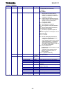
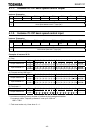
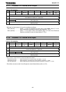
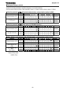
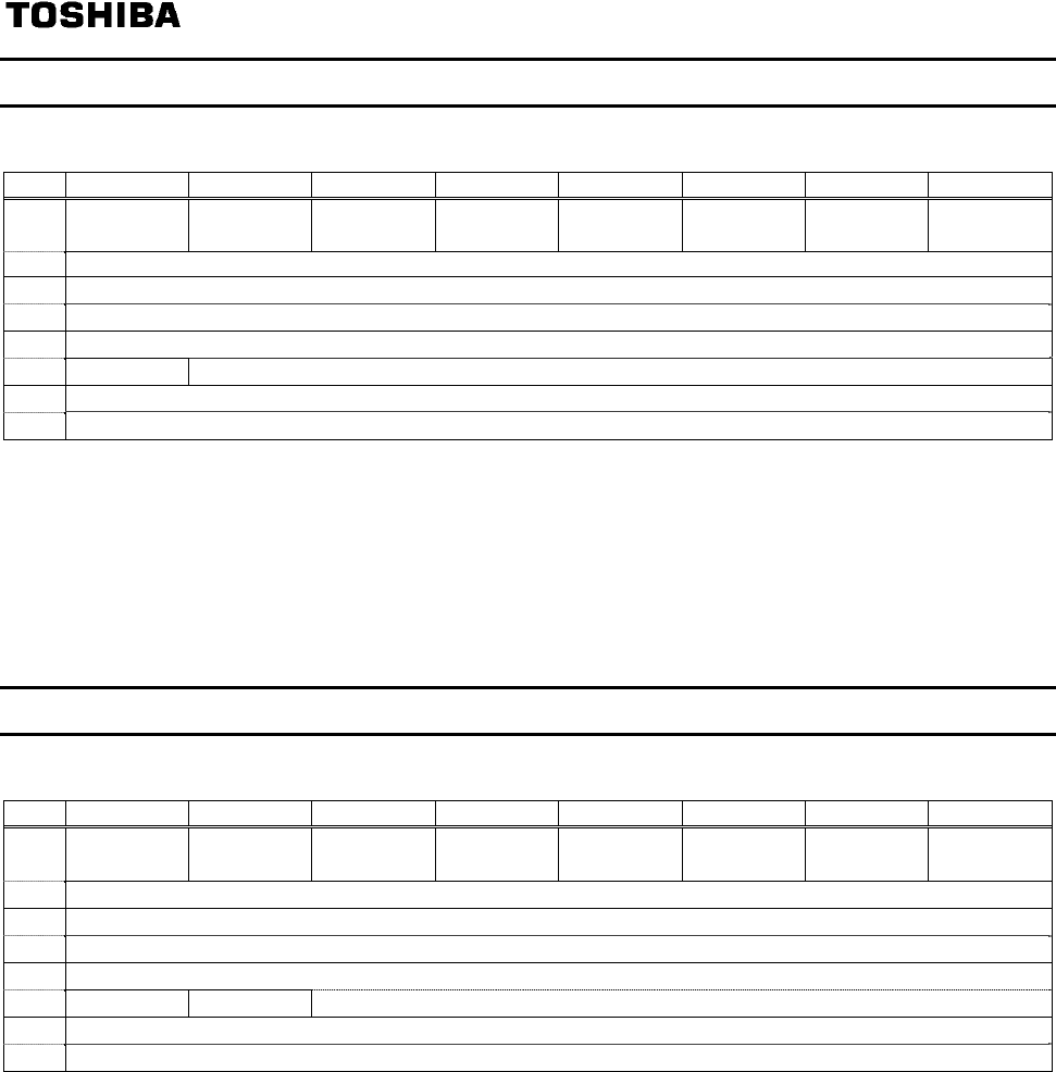
5.1.7. Instance 101: Native drive output
Instance 101 mapping
Byte Bit 7 Bit 6 Bit 5 Bit 4 Bit 3 Bit 2 Bit 1 Bit 0
0
- Net Ref
* Net Ctrl* - - Fault reset
Run
reverse
Run
forward
1 -
2
Drive Reference Speed min
-1
(Low byte)
3
Drive Reference Speed min
-1
(High byte)
4
Index (Low byte)
5
Write Index (High byte)
6
Data (Low byte)
7
Data (High byte)
* Bit 5 and 6 of the instance 101 byte 0 are defined as follows.
Bit 5 (Net Ctrl)................. When “1” is set, all commands of byte 0 and 1 are enabled. When “0” is set,
each command is according to setup of the parameter cmod.
Bit 6 (Net Ref)................. When “1” is set, bytes 2 and 3 are enabled. When “0” is set, Drive Reference
Speed is according to setup of the parameter fmod.
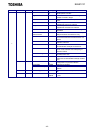
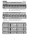
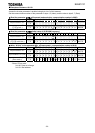
5.1.8. Instance 151: Native drive input
Instance 151 mapping
Byte Bit 7 Bit 6 Bit 5 Bit 4 Bit 3 Bit 2 Bit 1 Bit 0
0
At
reference**
Ref from
Net**
Ctrl from
Net**
Ready
Running
Reverse
Running
Forward
Warning
Faulted/
tripped
1
Drive Status *
2
Drive Actual Speed min
-1
(Low byte)
3
Drive Actual Speed min
-1
(High byte)
4
Index (Low byte)
5
Write Error Index (High byte)
6
Data (Low byte)
7
Data (High byte)
** Bit 5, 6, and 7 of the instance 151 byte 0 are defined as follows.
Bit 5 (Ctrl from Net)..............When command from communication is enabled, “1” is set.
Bit 6 (Ref from Net)..............When frequency command from communication is enabled, “1” is set.
Bit 7 (At reference) ..............When output frequency becomes the same as frequency command, “1” is set.
* Drive Status is same as the Control Supervisor class State attribute (refer to 4.6.2).