


14
5. Installing the Gateway
The gateway’s installation procedure will vary slightly depending on the chosen
mounting method and the networks that will be used.
5.1 RS-485 Network in Use
Note that in order to power the unit when not connecting to Toshiba ASDs via
the common serial ports, the optional 120VAC/9VDC power supply (ICC part
number 10456) or a user-supplied power source meeting the requirements
outlined in section 12 must also be installed.
1. Mount the unit via the desired method (refer to page 12 for more
information).
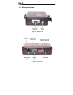
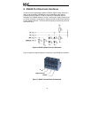
2. Connect the Modbus Plus network to the “NETWORK” DB9 connector. Be
sure to follow all published guidelines pertaining to Modbus Plus network
connections, layout and routing.
3. Connect the RS485 network to the pluggable terminal block. Refer to
section 6 for detailed connection information. Ensure that the terminal
block is fully seated into the terminal block header, and route the network
cable such that it is located well away from any electrical noise sources,
such as ASD input power or motor wiring. Also take care to route the
cable away from any sharp edges or positions where it may be pinched.
4. Take a moment to verify that the gateway and all network cables have
sufficient clearance from electrical noise sources such as drives, motors, or
power-carrying electrical wiring.
5. Connect the power supply to the gateway’s “POWER” jack.