


62
16.1.1 MSTR Parameters
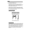
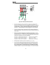
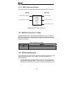
• The number in the top portion of the MSTR block is the address of the first
of six registers in the Control Block, and is generally configured as
indicated in Table 7.
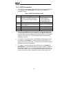
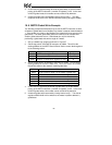
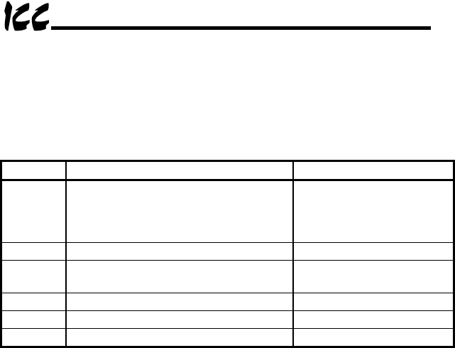
Table 7: MSTR Control Block Format
Address Description Parameters
4x Identifies which MSTR function is to be
executed. The MBP-100 supports
read, write, global read, and global
write.
1 = Write Registers
2 = Read Registers
5 = Write Global Data
6 = Read Global Data
4x + 1 Error code (Hex) Read Only
4x + 2 Number of consecutive registers to
read or write (n)
1 <= n <= # data registers
4x + 3 Starting register (s) 1 <= s <= (65535-n)
4x + 4 Destination node address 2 – 64
4x + 5 Master node address 1
There are small differences in the Control Block configuration depending
on the selected MSTR function and whether or not network elements such
as routers exist. Specific examples of each MSTR function can be found in
sections 16.3 through 16.6. These examples assume a single network
segment (no routers).
• The number in the middle portion of the MSTR block is the address of the
first register in the Data Area. For write functions, the Data Area is the
location of the source (write) data. For read functions, the Data Area is the
destination of the returned read data.
• The number in the bottom portion of the MSTR block is the Number of
Data Registers. This number defines the maximum number of registers in
the data area. Register “4x + 2” in the Control Block must be less than or
equal to this number. Also, each individual MSTR function has a maximum
value for this number, which is discussed in sections 16.3 through 16.6.