


16
4. Remove the drive’s front cover / open the drive’s cabinet door (refer to the
appropriate drive manual for instructions how to do this).
5. The drive’s LCD panel (also called the “Electronic Operator Interface” or
“EOI”) can communicate with the drive via either the RS485/RS232
channel (CNU1/CNU1A) or the common serial channel (CNU2/CNU2A).
Because the gateway uses the common serial channel, the LCD panel
must be configured to use the RS485/RS232 channel. If the drive to be
connected is currently using CNU2 (on the drive control board) and
CNU2A (on the LCD panel), then this connection must first be switched
over to CNU1 (on the drive control board) and CNU1A (on the LCD panel).
Refer to Toshiba’s documentation for any precautions or notices regarding
this connection change. If the LCD panel is already connected via the
RS485/RS232 channel, then no change is required.
6. Configure the drive’s LCD panel to communicate via the RS485/RS232
channel by setting parameter ”Communication Setting
Parameters...Communication Settings...Select LCD Port
Connection” to “RS485/232 serial”.
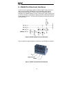
7. Connect the drive’s common serial communication port (CNU2) to one of
the ASD channels of the gateway with the communication cable
(communication cable is not included with the gateway kit). When
choosing cables for this connection, standard 24 AWG category 5 (CAT5)
unshielded twisted-pair (UTP) 8-conductor cables found in Ethernet
networks in most office environments can be used. The maximum
allowable length for these cables is 5 meters. Although there are many
varieties and styles of CAT5 UTP cables available, ICC strongly
recommends using only high-quality cables from reputable manufacturers
to guarantee optimal noise immunity and cable longevity. Ensure that each
end of the cable is fully seated into the modular connectors, and route the
cable such that it is located well away from any drive input power or motor
wiring. Also take care to route the cable away from any sharp edges or
positions where it may be pinched.
8. Reinstall the drive’s front cover / close the drive’s cabinet door.
9. Repeat steps 2-8 to connect other drive(s) as needed.
10. Connect the Modbus Plus network to the “NETWORK” DB9 connector. Be
sure to follow all published guidelines pertaining to Modbus Plus network
connections, layout and routing.
11. If an auxiliary power supply is going to be used, connect it to the gateway’s
“POWER” jack.
12. Take a moment to verify that the gateway and all network cables have
sufficient clearance from drives, motors, or power-carrying electrical wiring.
13. Turn the power sources to all connected drives ON, and verify that the
drives function properly. If the drives do not appear to power up, or do not
function properly, immediately turn power OFF. Repeat steps 2 and 3 to
remove all power from the drives. Then, verify all connections. Contact