


63
16.1.2 MSTR Inputs and Outputs
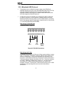
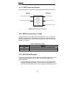
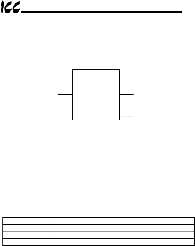
Figure 38 indicates the inputs and outputs associated with MSTR instructions.
Activate MSTR Instruction
Instruction End - Error
Instruction End - No Error
MSTR Instruction
40050
(Control Block)
40100
(Data Area)
100
(# data registers)
Instruction Active
INPUTS OUTPUTS
Terminate MSTR Instruction
Figure 38: MSTR Inputs and Outputs
16.2 MSTR Function Error Codes
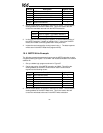
Table 8 indicates the error codes that may be output in the “4x+1” location of
the MSTR control block. These specific error codes can be generated by the
MBP-100. Additional error codes may be generated from other sources on the
Modbus Plus network.
Table 8: MSTR Error Codes
Error Code (Hex) Meaning
3001 Slave device does not support the requested function
3002 Nonexistent slave device registers requested
3003 Invalid data value requested
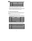
16.3 MSTR Read Example
The following example demonstrates how to use the MSTR instruction to read 2
registers starting at register 1 from an MBP-100 located at Modbus Plus
network address 2.
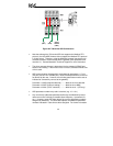
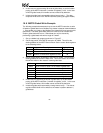
1. Set up a ladder logic program as shown in Figure 37. Set the top portion
of the MSTR Instruction to 40050. This will be the starting address of the
MSTR Control Block. Set the control block registers to the following values: