


58
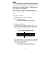
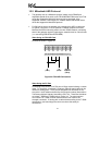
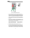
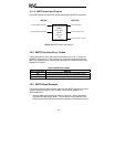
Connect as shown in Figure 35.
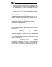
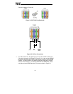
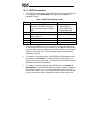
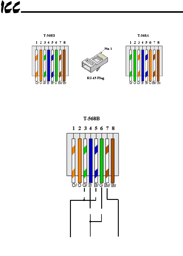
Figure 34: EIA/TIA Wiring Standards
RDA SDA
Signal
Ground
(TB:3)
B
(TB:2)
SDB RDB
A
(TB:1)
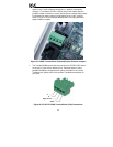
Figure 35: PU Port Connections
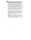
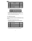
• For 700-series drives, the gateway can connect to the ASD via either the
PU (panel) connector as indicated in Figure 35, or via the on-board RS485
terminals. Because both of these ports externally present a 4-wire RS485
network, connecting them to the gateway requires jumpering the network
wires for 2-wire format (i.e. connecting SDA-RDA and SDB-RDB). When
using the on-board RS485 terminals, connect as shown in Figure 36.