


64
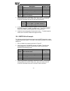
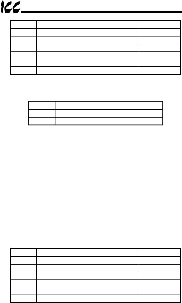
Address Description Register Value
40050 MSTR function (read) 2
40051 Error code Read Only
40052 Number of consecutive registers to read 2
40053 Starting register 1
40054 Destination node address 2
40055 Master node address 1
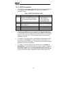
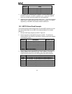
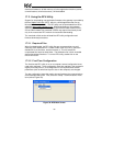
2. Set the middle portion of the MSTR instruction to 40100. This will be the
starting address of the MSTR Data Area. This is the location that will
contain the read data returned from the MSTR transaction.
Address Value
40100 Value of register 1 @ network address 2
40101 Value of register 2 @ network address 2
3. In this case, we are accessing two registers, so set the bottom portion of
the MSTR instruction (“number of registers”) to 2. In the case of MSTR
reads, this number cannot be greater than 125 by definition.
4. Initiate the read command by closing internal relay 1. The data response
will be seen in the MSTR Data Area (register 40100).
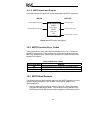
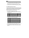
16.4 MSTR Write Example
The following example demonstrates how to use the MSTR instruction to write
4 registers starting at register 1 to an MBP-100 located at Modbus Plus network
address 32.
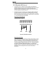
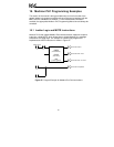
1. Set up a ladder logic program as shown in Figure 37.
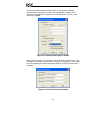
2. Set the top portion of the MSTR Instruction to 40060. This will be the
starting address of the MSTR Control Block. Set the Control Block
registers to the following values:
Address Description Register Value
40060 MSTR function (write) 1
40061 Error code Read Only
40062 Number of consecutive registers to write 4
40063 Starting register 1
40064 Destination node address 32
40065 Master node address 1
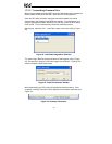
3. Set the middle portion of the MSTR instruction to 40200. This will be the
starting address of the MSTR Data Area. This is the location that will
contain the write data to be used in the MSTR write transaction.