4 Replacement Procedures 4.5 WLAN Card
NB250/NB255 Maintenance Manual 4-24
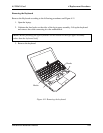
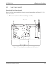
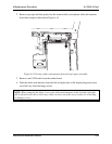
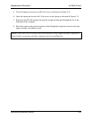
2. Remove any tape and then gently free the camera cable, microphone cable and antennas
from their trough as indicated in Figure 4.14.
Figure 4.14 Freeing cables and antennas from the logic upper assembly
3. Remove one LVDS cable from the motherboard.
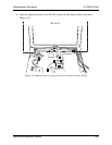
4. Take the cables and antennas from the left and right sides of the display hinge and move
out of the way from the hinge screws.
NOTE: When removing the hinge screws, the cables and antennas on the left and right sides
will be obstacles. Be sure to move any cables securely out of the way to ensure no scratching
or damage occurs.


