


Overview 12
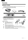
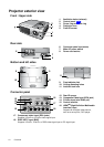
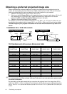
Projector exterior view
Front / Upper side
Rear side
Bottom and left sides
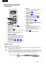
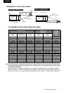
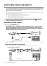
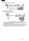
Connector panel
1. Ventilation holes (exhaust)
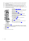
2. Control panel
3. Focus ring and zoom ring
4. Projection lens
5. Front IR sensor
6. Connector panel (see below)
7. Main AC power switch
8. Power cord socket
9. Front adjuster feet
10. Ceiling mounting holes
11. Antitheft lock hole
12. Rear IR sensor
13. Composite Video input (RCA jack)
14. S-Video input (mini DIN 4-pin)
15. Control terminal
16. HDMI
TM
(High-Definition Multimedia
Interface) input
Supports an all-digital video source,
such as a set-top box, DVD player.
17. Component video input (RCA jacks)
Supports Y/PB/PR or Y/CB/CR video signal input.
18. RGB/ HDTV input (BNC)
Supports Y/PB/PR, Y/CB/CR, or RGB video signal input or PC signal input.
1
3
4
2
5
p.13
HDMI
P
R / CR
PR/R
P
B / CB
Y
P
B/B
Y/G
COMPONENT 1
COMPONENT 2 / GBR
VIDEO
S-VIDEO
CONTROL
VD
HD
6
7
8
9
9
10
10
11
HDMI
P
R / CR
PR/R
P
B / CB
Y
P
B/B
Y/G
COMPONENT 1
COMPONENT 2 / GBR
VIDEO
S-VIDEO
CONTROL
VD
HD
14
17
18
12
15
16
13