


- 45 -
6 F 3 H 1 0 0 1
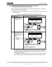
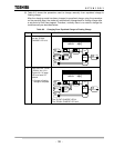
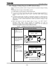
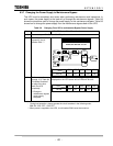
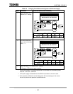
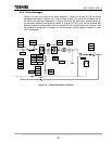
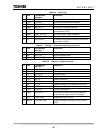
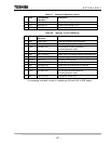
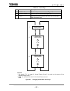
9.2.3 Failure Messages
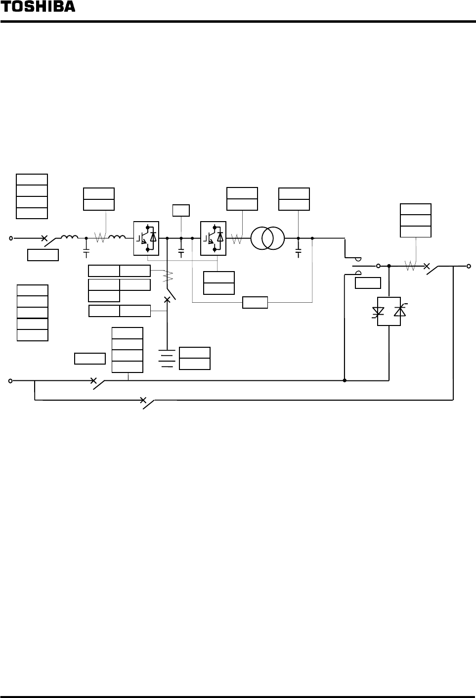
Figures 9.6 show the locations for failure detection. Tables 9.4 through 9.8 list the failure
messages described in Section 9.2.1 "Failure Data Screen". The content and display text for
the failure and warning messages in Tables 9.4 through 9.8 have been created based on
the standard protective configuration shown in Figures 9.6.UPS units can be shipped with
different protective configurations from the standard if this is specified by the customer. See
the protective configuration indicated on the elementary wiring diagram created for each
UPS unit shipped.
Figure 9.6 Protective Detector Locations
95S
27S
59S
52RT
51CO
51C
52R
30MU
86MU
48S
76CH 76
72BO 72BT
80B1 80B2
CONVERTER
INVERTER
47C
59C
27C
45
51IO
59I
27I
51L1
51L
49H
52L
5E
80PS
26C
UPS
52C
52M
47R
52CO
26B
33B
83F
71BF
WDCPU
WDDSP
95C
51I