


80
81
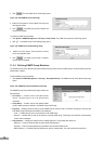
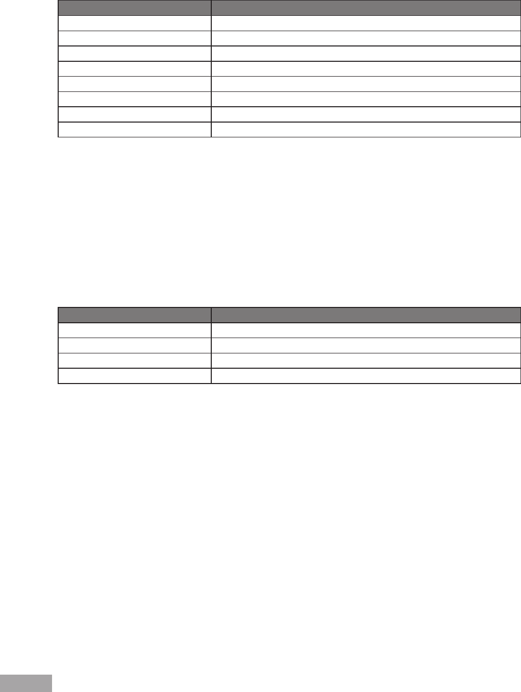
The following table contains the VPT to Queue default settings:
Table 7: VPT Default Mapping Table
VPT Value Queue Number
0 2
1 1
2 1
3 2
4 3
5 3
6 4
7 4
Mapping of the VPT to the output queue is performed on a system-wide basis, and can be enabled or disabled per port.
Default CoS— Packets arriving untagged are assigned to a default VPT, which can be set by the user on a per port
basis. Once the VPT is assigned, the packet is treated as if it had arrived with this tag. The VPT mapping to the output
queue is based on the same user-dened 802.1p tag-based denitions.
DSCP — Users can congure the system to use the IP DSCP of the incoming packet to the output priority queues. The
mapping of the IP DSCP to priority queue is set on a per system basis. If this mode is active, a non-IP packet is always
classied to the best effort queue.
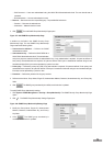
The default mapping is shown in the following table:
Table 8: DSCP Default Mapping Table
DSCP Value Queue Number
0-15 q1 (lowest priority)
16-31 q2
32-47 q3
48-64 q4
All network trafc which is not assigned a DSCP value is forwarded with Best Effort service.
After packets are assigned to a specic queue, using the chosen classication method various services can be applied.
Scheduling for output queues can be congured, including:
Strict priority
Weighted Round Robin (WRR)
Scheduling schemes are specied per system. WRR weights to the queues can be assigned in any order. For each interface
or queue, the following output shaping can also be congured:
Committed Burst Size (CBS)
Committed Information Rate (CIR)
Actions for over-the-limit trafc
12.1.2 QoS Modes
The device supports the following QoS modes:
Basic QoS Mode
Advanced QoS Mode