


Basic Configuration via Browser Interface
Trango Broadband Wireless — Access5830 User Manual Rev. F page 17
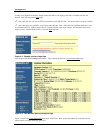
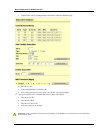
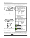
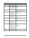
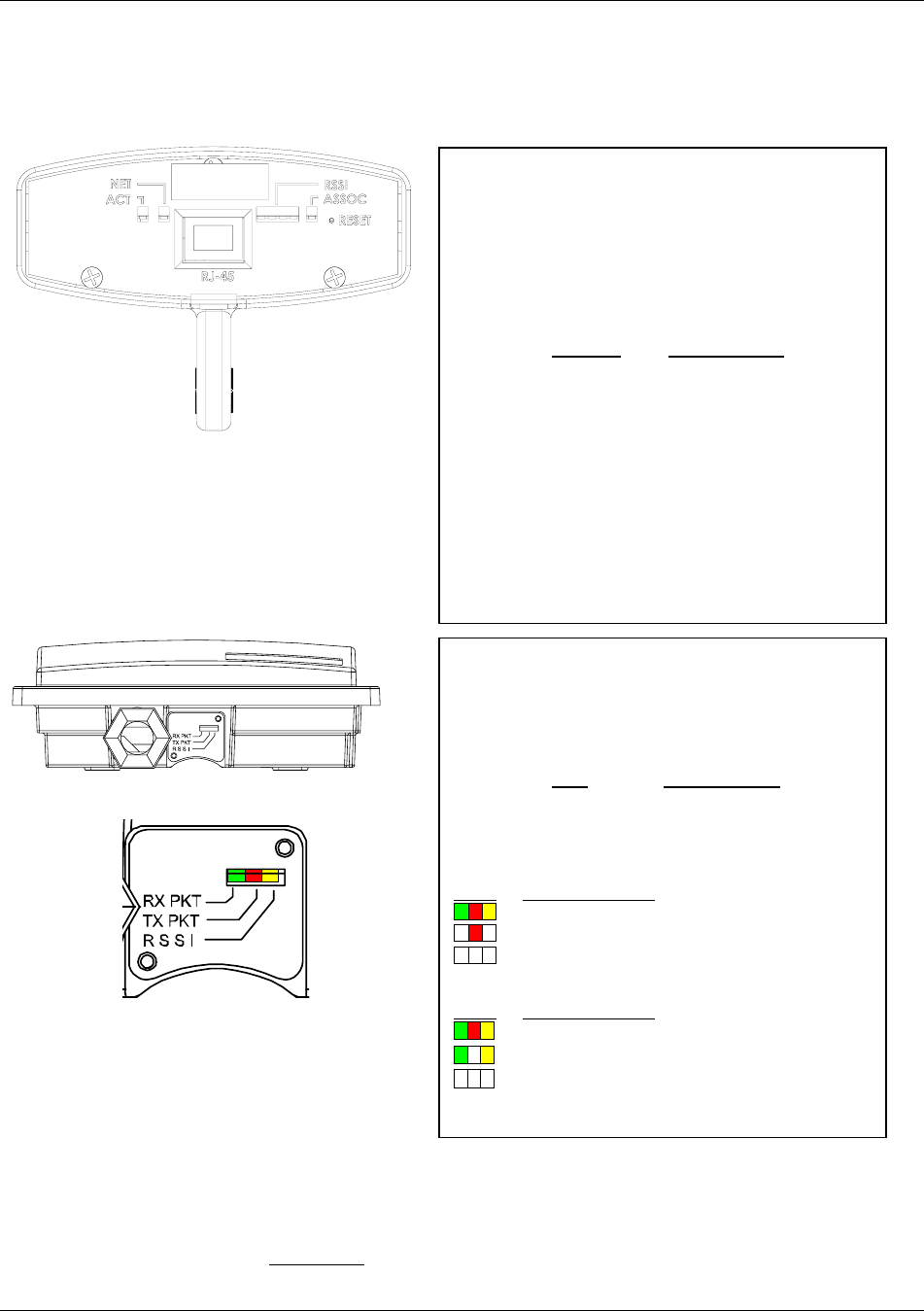
M5830 LED Guide
Rx/Green – Indicates RF (wireless) receive activity
Tx/Red – Indicates RF (wireless) transmit activity
RSSI/Yellow – Relative Signal Strength Indicator
LED
Signal Strength
Not Lit < -80 dBm
Blinking > -80 dBm < -65 dBm
Solid > -65 dBm
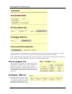
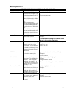
M5830S-AP -60
LEDs
State of the Radio
Associated (Green and Yellow may be blinking)
AP is transmitting, but nothing is associated
No power or Opmode “OFF”
M5830S-SU and M5830S-SU-EXT
LEDs
State of the Radio
Associated (All may be blinking)
SU is receiving, but not associated
No power, Opmode “OFF,” or No AP present
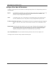
LED Summary
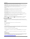
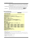
At this point it is useful to learn about the various LEDs, which can be found on the bottom of Access5830 radios (both
M5830 series and FOX series). These LEDs can assist the user in determining radio and link status.
XX-XX-XX
|||||||||||||||||||||||||||||||||
0001DE FF FF FF
MAC:
TEST DATE:
S/N: XXXXXXXXXX
|||||||||||
M5300S-FSU
Figure 5-1: Bottom of FOX Radio with LEDs
Figure 5-2: Bottom of M5830 Radio with LEDs
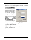
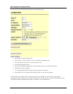
Evaluate Link Quality
It takes approximately 60 seconds for the radios to complete the boot-up cycle, which includes switching on the Opmode,
handshaking, and association. If more than one scan channel exists in the SU Scan Table, or if the AP is busy servicing
many SUs, the association process may take slightly longer. The radio’s firmware includes several useful tools to assist
in determining which SUs are associated, and the quality of each link. The LEDs are a quick method for verifying link
quality. Another useful tool is the Link Control
page.
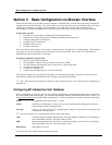
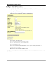
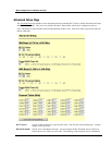
FOX Series Radio LED Guide
ACT – Indicates Ethernet Receive/Transmit activity.
N
ET – This LED lights when connected to a 100 BaseT
network. The LED remains unlit when connected
to a 10 BaseT network
RSSI – Relative Signal Strength Indicator. See page
Antenna Alignment section for more details.
Lit LEDs Signal Strength
0 LED -80 dBm
1 LED -75 dBm
2 LED -70 dBm
3 LED -65 dBm
4 LED -60 dBm or greater
ASSOC – This LED indicates one of four statuses:
1. Off - when there is no power at the radio.
2. Blinks once every second - unit is powered on,
but in Opmode “OFF.”
3. Blinks twice per second - unit is in Opmode
“SU,” and is scanning for an AP.
4. Solid On - unit is associated with an AP.