


Table of Figures Trango
Trango Broadband Wireless — Access5830 User Manual Rev. F page iii
Table of Figures
Figure 1-1: Typical Point-to-Multipoint Deployment.................................................................................................... 1
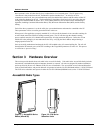
Figure 2-1: Access5830 Series Radios (AP and SU)...................................................................................................... 2
Figure 2-2: FOX Series Subscriber Units ....................................................................................................................... 2
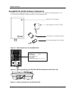
Figure 2-3: Basic Components of an Access5830 Radio............................................................................................... 4
Figure 2-4: Bottom of Access Point (and 5830 Series SU) Shows Access Cover with LEDs....................................... 4
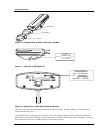
Figure 2-5: Components of FOX Series Subscriber Units............................................................................................. 5
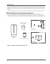
Figure 2-6: Exploded View of Radio, Foam Insert, and Boot ....................................................................................... 6
Figure 2-7: Side View of FOX Series SU...................................................................................................................... 6
Figure 2-8: Bottom View of FOX Series SU (Boot Removed)...................................................................................... 6
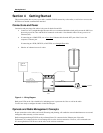
Figure 3-1: Wiring Diagram .......................................................................................................................................... 7
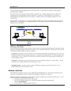
Figure 3-2: Radio Management Methods ...................................................................................................................... 8
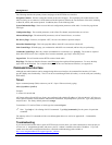
Figure 3-3: Browser Interface Login Page..................................................................................................................... 9
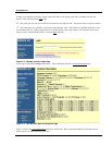
Figure 3-4: Web Browser System Information Page ..................................................................................................... 9
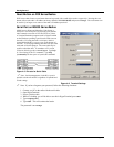
Figure 3-5: Pin-outs for Serial Cable............................................................................................................................ 11
Figure 3-6: Terminal Settings...................................................................................................................................... 11
Figure 4-1: Bottom of FOX Radio with LEDs............................................................................................................. 17
Figure 4-2: Bottom of M5830 Radio with LEDs......................................................................................................... 17
Figure 6-1: M5830 Mounting Hardware Assembly..................................................................................................... 28
Figure 6-2: Alternative Mounting................................................................................................................................ 28
Figure 6-3: Articulation for M5830S-AP with Mono Pod Mount (not supplied) ........................................................ 29
Figure 6-4: FOX Series SU Pole Mount (1” – 2” Diameter) ....................................................................................... 30
Figure 6-5: FOX Series SU Wall Mount ..................................................................................................................... 30
Figure 6-6: FOX5800-D with Mounting Cradle for DSS Dish Antenna ..................................................................... 31
Figure 6-7: FOX5800-D / AD5800-25 Reflector Dish on Pole................................................................................... 31
Figure 6-8: FOX5800-D / AD5800-25 Reflector Dish on Wall................................................................................... 32
Figure 6-9: Grounding Example for M5830 Series ..................................................................................................... 32
Figure 6-10: Cat-5 Cable Strain Relief ........................................................................................................................ 33
Figure 6-11: Grounding with Drain Wires of Shielded Twisted Pair Cat-5 Cable ...................................................... 33
Figure 7-1 Default Channel Table (MHz)..................................................................................................................... 36
Figure 8-1: Typical Radio System................................................................................................................................ 66
Figure 8-2: Attenuation of an RF signal ....................................................................................................................... 67
Figure 8-3: Radiation Pattern of Directional Antenna ................................................................................................. 68
Figure 8-4: Multipath Reception................................................................................................................................... 69
Figure 8-5: Fresnel Zone Obstruction........................................................................................................................... 69
Figure 8-6: Fresnel Zone Radius Calculation ............................................................................................................... 70
Table of Tables
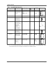
Table 1: Access5830 Radio Description........................................................................................................................ 3
Table 2: Reference Table of Basic AP System Information ........................................................................................ 22
Table 3: Reference Table of Basic SU System Information ........................................................................................ 25