


Management
Trango Broadband Wireless — Access5830 User Manual Rev. F page 67
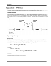
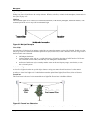
Figure 9-2: Attenuation of an RF signal
P
in is the incident power level at the attenuated input. Pout is the output power level at the attenuated output. Attenuation is
expressed in dB as follows:
PdB = -10 x Log (Pout/Pin)
For example: If, due to attenuation, half the power is lost (Pout/Pin = 1/2), attenuation in dB is:
-10 x Log (1/2) = 3dB
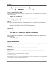
Path Loss
It is the loss of power of an RF signal traveling (propagating) through space. It is expressed in dB. Path loss depends on:
• The distance between transmitting and receiving antennas
• Radio line of sight clearance between the receiving and transmitting antennas
• The precision with which the antennas are aimed
Free Space Loss
Is the attenuation of an electromagnetic wave while propagating through space. This attenuation is calculated using the
following formula:
Free space loss = 32.4dB + 20xLog(FMHz) + 20xLog(RKm)
Where F is the RF frequency expressed in MHz, R is the distance between the transmitting and receiving antennas. At 5.8
GHz, this formula is:
100+20xLog(RKm)
Antenna Characteristics
Isotropic Antenna
Is a hypothetical antenna having equal radiation intensity in all directions. It is used as a zero dB gain reference in radiated
power calculations (gain).
Antenna Gain
A measure of radiated power relative to an isotropic antenna. Antenna gain is expressed in dBi.
Radiation Pattern
A graphical representation in either polar or rectangular coordinates of the spatial energy distribution of an antenna.
Side Lobes
The radiation lobes in any direction other than that of the main lobe.
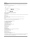
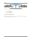
Omni-directional Antenna
Radiates and receives equally in all directions (in azimuth and elevation). The following diagram shows the radiation pattern
of an omni-directional antenna with its side lobes in polar form.