


Connection Schemes
TM-DIOP-01XN-01 2-15
Connection Schemes
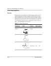
Stand-Alone Operation
A 120 Ohm resistor should be connected across the CAN-hi and CAN-lo
terminals to properly terminate the bus. No other connections to this port
are necessary for single unit operation.
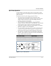
Parallel Operation
When operated in this mode, up to ten XDI inverters can operate on a
single bus by daisy chaining the canbus lines. Any additional units above
this will still operate autonomously and not participate in load sharing
arbitration. At power-up, the first ten units to access the bus acquire a
unique I.D. each, beyond which no more I.D.s are made available. No
unique master exists in a parallel system. All units continuously execute a
complex algorithm to determine the load current based on the number of
units online and the highest individual current. This ensures no
interruption to the load should any unit in the system fail or is turned off.
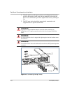
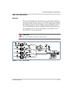
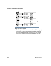
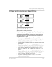
Connection
• Make connections to the CAN/SYNC connector using its screw-type
wire clamps. It may be necessary to remove the mating connector to
facilitate connections to the terminal. Daisy chain the CAN-bus lines
across all units in parallel (i.e. all CAN-hi terminals are connected
together and likewise for CAN-lo). 120 Ohm terminating resistors
must be connected across the CAN terminals of the first and last units
in the chain.
• Also daisy chain the “SYNC-OUT 0” and “return” terminals on the
connector. This provides phase lock between paralleled units. See
Figure 2-8.
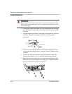
CAUTION
Before attempting any connections, ensure power to rack is off by de-energizing
input and output circuit breakers.
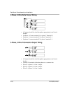
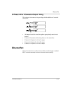
This section covers the realization of different output configurations available
with this product line.