


3-Phase Synchronization and Signal Wiring
TM-DIOP-01XN-01 2-19
3-Phase Synchronization and Signal Wiring
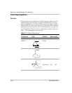
Refer to Table 2-2 for the signal pinouts.
To achieve proper three-phase output, units configured for each phase
need to be wired to the appropriate phase. Extra care should be exercised
when multiple paralleled units are also wired for 3-phase operation. In
this case it is advisable to group all parallel inverters belonging to the
same phase together in a rack.
• First ensure power to the rack has been disconnected. Make
connections to the CAN/SYNC connector using its screw-type wire
clamps. It may be necessary to remove the mating connector to
facilitate connections to the terminal.
• Twisted bundles of four multi-colored wires should be used for easier
identification.
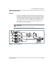
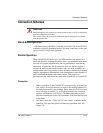
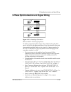
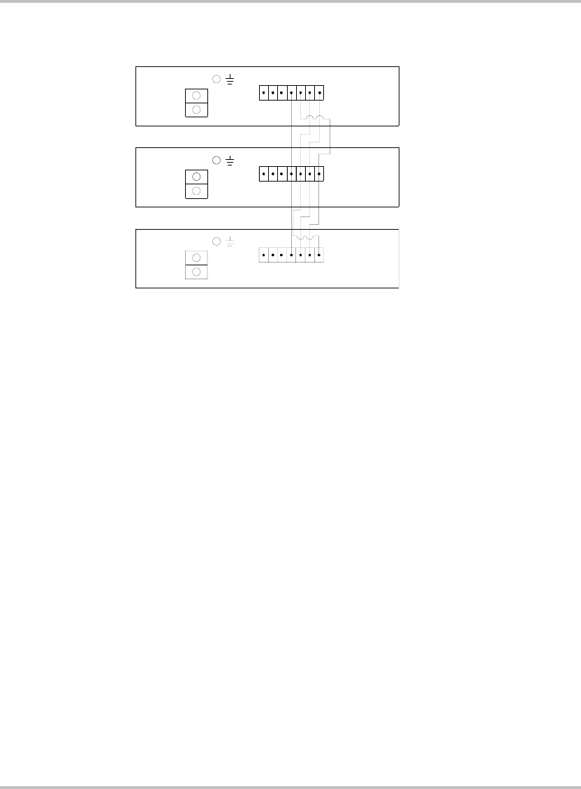
• Start with unit in Phase-1, wire from “SYNC-OUT 0” in this phase to
“SYNC-OUT 120” of Phase-2 and “SYNC-OUT 240” of Phase-3.
• Next, Connect a different color wire from “SYNC-OUT 120” of
Phase-1 to “SYNC-OUT 240” of phase-2 and “SYNC-OUT 0” of
Phase-3.
• Connect a different color wire from “SYNC-OUT 240” of Phase-1 to
“SYNC-OUT 0” of phase-2 and “SYNC-OUT 120” of Phase-3.
• Lastly, connect all “RETURN” lines together.
• See section on “Parallel Operation” on page 2–15 to connect
additional units to each phase.
Figure 2-10
3-Phase Sync Connection
1
4
7
5
36
2
L1
L2
L1
L2
26
3
5
7
41
4
7
5
3
6
21
L2
L1