


Inverter Module Installation and Operation
3-6 TM-DIOP-01XN-01
User Interface
Front Panel
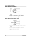
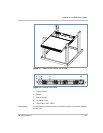
User Lines
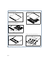
The port with user lines is located at the rear panel of the rack mount
frame (Figure 2-3). See Figure 2-7. The following table lists the signals:
Table 3-1
Front Panel LED Functions
Red LED Green LED Function
ON OFF A continuously incompatible operating condition
exists and an alarm has tripped. See “Protections
and Alarms” on page 3–7). The inverter is
automatically turned off until the fault/alarm has
been cleared.
OFF ON Regular operating conditions. Output is on and
delivering power.
OFF fast flashing Self-Diagnostic mode. Prior to enabling the
inverter the unit always performs a self-check and
diagnostics.
OFF slow-short flash Stand-by mode.
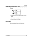
Table 3-2
User Line Pins
Pin Name Function
1 User_Ground All user lines are referenced to user_gnd. User_gnd is
isolated from both the input DC power and the output AC
power.
2 Shut_Down This is an input pin. The input impedance is 100 Ω in
parallel with 20 pF. A logic high (1.25 V to 5 V) would set
the inverter into Standby Mode (see page 3–5). If pin 2 is
floating, the internal pull_down resistor of 100 Ω will
force a logic “0” and this pin becomes inactive.
3 Fault_Flag This is an output pin. A logic high (5 V) indicates that an
alarm has tripped. The output of the inverter is, therefore,
disabled.
4 Auxiliary_Line This is an output pin. The functionality of this user line is
factory preset. It can be user configured if the Ethernet
option is installed.
5 Inverter_On This is an output pin. A logic high (5 V) indicates that the
inverter is in an “on” state and delivering AC power to the
AC output power terminal.