


Connection Schemes
TM-DIOP-01XN-01 2-17
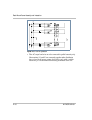
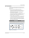
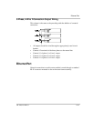
Split Phase Operation
Use this scheme to extend the output voltage. No more than two units
should be connected in series though more can be added in parallel with
either series unit.
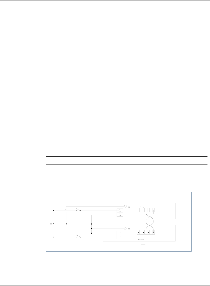
To connect two units for split voltage, proceed as follows:
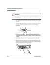
• First ensure power to the rack has been disconnected. make
connections to the CAN/SYNC connector using its screw-type wire
clamps. It may be necessary to remove the mating connector to
facilitate connections to the terminal
• Start with the phase synchronizing lines on the CAN/SYNC
connector. Wire the “SYNC_OUT 0” and “RETURN” of the first unit
in the top phase to those of the first unit in the bottom phase.
• To add units in parallel on either top or bottom phase, see “Parallel
Operation” on page 2–15 for wiring details.
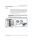
• To create the Split-voltage between the top phase and bottom phase,
connect the L2 terminals of the first group to L1 terminals of the
second group. This node must also be connected to safety ground.
• This leaves L1 of top phase and L2 of bottom phase as the output
terminals. These should be connected to the load or distribution bus
using a suitably rated circuit breaker.
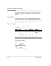
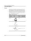
Load Terminal Voltage Output Voltage
120 V model 230 V model
Terminal - Terminal (L1-L2) 240 460
Terminal - Chassis (L1-GND or L2-GND) 120 230
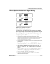
Figure 2-9
Split-Phase Operation
L1
L2
UNIT 2
UNIT 1
26
3
5
7
4
1
4
7
5
36
21
L2
L1
L1
L2
TO TOP PARALLEL UNITS
TO BOTTOM PARALLEL UNITS
2-POLE BREAKER