


152 www.xilinx.com Ethernet 1000BASE-X PCS/PMA or SGMII v9.1
UG155 March 24, 2008
Chapter 9: Configuration and Status
R
These signals may be changed by the user application at any time. The Clock Domain
heading denotes the clock domain the configuration signal is registered in before use by
the core. It is not necessary to drive the signal from this clock domain.
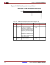
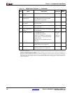
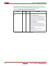
Table 9-36: Optional Configuration and Status Vectors
Signal Direction
Clock
Domain
Description
configuration_vector
[3:0]
Input See
note 1
Bit[0]: Reserved (currently unused)
Bit[1]: Loopback Control
• When used with a RocketIO transceiver, the
core is placed in internal loopback mode.
• With the TBI version, Bit 1 is connected to
ewrap. When set to ‘1,’ this indicates to the
external PMA module to enter loopback mode.
See “Loopback,” page 197.
Bit[2]: Power Down
• When a RocketIO transceiver is used, a
setting of ‘1’ places the RocketIO in a low-
power state. A reset must be applied to clear.
• With the TBI version, this bit is unused.
Bit[3]: Isolate
• When set to ‘1,’ the GMII should be
electrically isolated.
• When set to ‘0,’ normal operation is enabled.
1. Signals are synchronous to the core’s internal 125 MHz reference clock; this is userclk2 when used
with a RocketIO transceiver; gtx_clk when used with TBI.